| CPC G05D 1/0094 (2013.01) [B64C 39/06 (2013.01); B64U 2101/00 (2023.01)] | 14 Claims |

|
1. An unmanned aerial vehicle (UAV)-assisted hanging ring robot for live installation and grounding, used together with a UAV, and comprising:
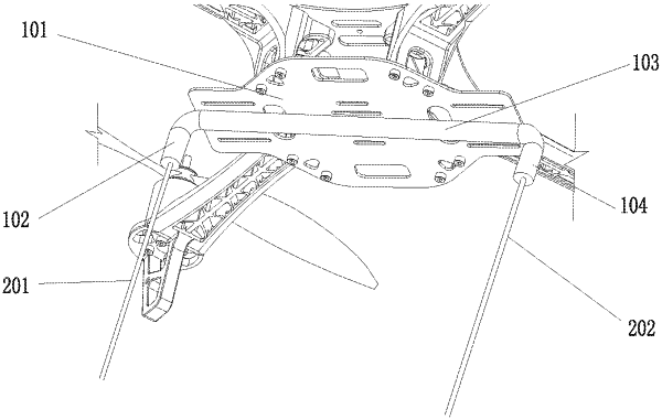
a hanging tray, a wire hanging bracket, a hanging wire, an overturning stay wire, an overturning frame, a support, an electric lock, a walking wheel, a driving motor, a workbench, a clamp seat, a puncture clamp, a tightening mechanism, a remote controller, and a controller, wherein
the hanging tray is installed at a bottom of the UAV, the wire hanging bracket is fixedly connected to the hanging tray, and the hanging wire is connected to the wire hanging bracket;
both the support and the clamp seat are installed on the workbench, the overturning frame is rotatably installed on the support, the electric lock is installed on the support, the overturning frame is provided with a lockhole matching the electric lock, one end of the overturning stay wire is connected to the overturning frame, the other end of the overturning stay wire hangs on ground, the walking wheel is rotatably installed on the overturning frame, the driving motor is installed on the overturning frame, and the walking wheel is connected to the driving motor;
the puncture clamp is installed on the clamp seat, and the tightening mechanism is installed on the workbench and connected to a tightening screw of the puncture clamp; and
the electric lock, the tightening mechanism, the driving motor, and the remote controller are connected to the controller.
|