US 12,235,494 B2
Managed connectivity in fiber optic systems and methods thereof
Mark Smrha, West Chicago, IL (US); Michael D. Schroeder, Webster, MN (US); Michael Gunderson, Shakopee, MN (US); and Vern Loch, Prior Lake, MN (US)
Assigned to CommScope Technologies LLC, Hickory, NC (US)
Filed by CommScope Technologies LLC, Hickory, NC (US)
Filed on Apr. 17, 2023, as Appl. No. 18/301,607.
Application 14/062,204 is a division of application No. 12/905,658, filed on Oct. 15, 2010, granted, now 8,596,882, issued on Dec. 3, 2013.
Application 18/301,607 is a continuation of application No. 17/582,258, filed on Jan. 24, 2022, granted, now 11,630,269.
Application 17/582,258 is a continuation of application No. 16/895,494, filed on Jun. 8, 2020, granted, now 11,231,555, issued on Jan. 25, 2022.
Application 16/895,494 is a continuation of application No. 15/804,022, filed on Nov. 6, 2017, granted, now 10,678,001, issued on Jun. 9, 2020.
Application 15/804,022 is a continuation of application No. 14/930,067, filed on Nov. 2, 2015, granted, now 9,810,860, issued on Nov. 7, 2017.
Application 14/930,067 is a continuation of application No. 14/062,204, filed on Oct. 24, 2013, granted, now 9,176,294, issued on Nov. 3, 2015.
Claims priority of provisional application 61/252,386, filed on Oct. 16, 2009.
Prior Publication US 2023/0324631 A1, Oct. 12, 2023
This patent is subject to a terminal disclaimer.
Int. Cl. G02B 6/38 (2006.01); G02B 6/44 (2006.01)
CPC G02B 6/3895 (2013.01) [G02B 6/3825 (2013.01); G02B 6/3897 (2013.01); G02B 6/4452 (2013.01); G02B 6/4455 (2013.01)] 20 Claims
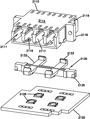
OG exemplary drawing
 
1. An optical connection module comprising:
a module body extending along a depth between a front and a rear, along a width between opposite first and second sides, and along a height between a top and a bottom;
a first mounting feature disposed at the first side of the module body;
an optical adapter carried by the module body, the optical adapter defining front ports accessible from the front of the module body;
a circuit board carried by the module body, the circuit board extending parallel with the top and bottom of the module body, the circuit board being disposed between the top and bottom of the module body, the circuit board carrying a plurality of spring contacts; and
a plurality of presence sensing members disposed at the front ports of the optical adapter, the presence sensing members being separate from the spring contacts, and the presence sensing members aiding in detecting plug connectors at the front ports.