| CPC G02B 21/0032 (2013.01) [G02B 21/0048 (2013.01); G02B 21/006 (2013.01); G02B 21/0076 (2013.01)] | 13 Claims |

|
1. A microscopic imaging system, the imaging system comprising:
a light source for generating illumination light;
an optical system;
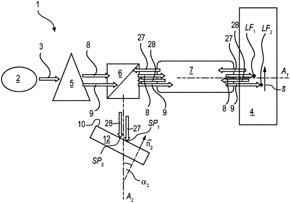
a detector system comprising light receiving portions (SP1, SP2) that are arranged in a common plane, wherein a normal (n2) to the common plane is arranged at an angle (α2) relative to the optical axis (A2) of the optical system along which detection light is incident on the light receiving portions (SP1, SP2), the angle (α2) dimensioned to at least partially compensate for an axial displacement of foci in an object;
wherein the optical system is configured:
to focus the illumination light to simultaneously form a plurality of foci within the object to be inspected so that the detection light is emitted by the object from the foci in response to the illumination light, wherein each of the foci is a line focus (LF1, LF2); and
to direct the detection light to the detector system, which is configured to detect the detection light;
wherein the optical system is further configured so that the foci, when seen relative to an optical axis (A1) of the optical system along which the illumination light is incident on the object, are mutually displaced from each other in an axial direction and mutually displaced from each other in a lateral direction;
wherein for each of the foci generated in the object, the detector system and the optical system are configured to substantially separately detect the detection light which is emitted from the respective focus;
wherein the optical system and/or the detector system are configured to compensate for the displacement along the axial direction so that for each of the foci, the light receiving portions (SP1, SP2) of the detector system which receives a portion of the detection light is substantially located at a position which is optically conjugate to at least a portion of the respective focus;
wherein the optical system comprises a beam multiplication system between the light source and the object, wherein the beam multiplication system is configured to generate a plurality of beamlets; and
wherein the beam multiplication system comprises a diffractive optical element, wherein each of the beamlets corresponds to a diffraction order of the diffractive optical element,
wherein the diffractive optical element is configured to at least partially compensate a spherical aberration of the optical system, wherein the spherical aberration affects a shape and/or a line width of at least one of the line foci (LF1, LF2),
wherein the diffractive optical element is configured so that illumination light, which exits from the diffractive optical element has a phase profile, measured in a diffraction plane of the diffractive optical element,
wherein the phase profile or an additive component of a polynomial representation of the phase profile has a substantially two-fold rotational symmetry.
|