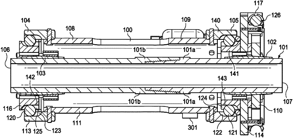
| CPC G01N 3/22 (2013.01) [G01N 3/10 (2013.01); G01N 3/20 (2013.01); G01N 2203/0019 (2013.01); G01N 2203/0021 (2013.01); G01N 2203/0023 (2013.01); G01N 2203/0028 (2013.01); G01N 2203/0048 (2013.01); G01N 2203/04 (2013.01)] | 18 Claims |

|
1. An apparatus for testing specimens comprising:
a torque transfer tubular having center axis, a first end, and a second end;
the first end of the torque transfer tubular having a clamp adapted to statically mount to a first location on a test specimen, wherein the clamp establishes a static contact between the torque transfer tubular first end and the test specimen;
the second end of the torque transfer tubular having a first circumferential plate and a second circumferential plate located proximate to the first circumferential plate and having a clamp adapted to statically mount to a second location on a test specimen, wherein a torque is generated in the test specimen between the first location and second location by generating a rotating displacement between the first circumferential plate and second circumferential plate about the center axis of the torque transfer tubular.
|