| CPC G01M 3/002 (2013.01) [G01M 3/2815 (2013.01)] | 5 Claims |
|
1. A pipeline potential safety hazard intelligent identification method integrating power frequencies, pressures and temperatures, comprising the following steps:
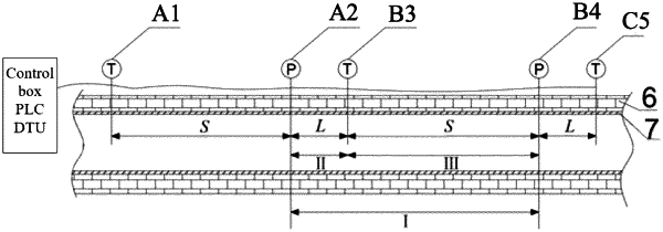
step 1, dividing leakage analysis units according to conditions of temperature sensors and pressure sensors arranged on a heating pipeline;
step 2, receiving, by a PLC, temperature values and pressure values collected by the temperature sensors and the pressure sensors in real time, performing early-stage theoretical analysis on energy at a leakage point; then analyzing and solving a pipeline leakage transient steam temperature and a pipeline leakage transient pressure;
step 3, based on the transient temperature and the transient pressure, positioning a leakage location by the PLC according to a pressure gradient method; and
step 4, performing, by the PLC, a pipeline leakage early warning and an on-off early warning of a heating supply pump unit;
wherein, in step 2, the process of analyzing and solving, by the PLC, a pipeline leakage transient steam temperature and a pipeline leakage transient pressure is specifically as follows:
at the moment of pipeline leakage, ToN=ToL=To, wherein ToN is a temperature of an outer wall of a pipeline in the case of no leakage, and the unit is K; ToL is a temperature of the outer wall of the pipeline in the case of leakage, and the unit is K; and To is a transient temperature of the outer wall of the pipeline, and the unit is K;
the pipeline leakage transient steam temperature Tm is calculated by a formula below:
 wherein, Ti is a temperature of fluid in the pipeline, and the unit is K; h is a convection heat transfer coefficient of steam and a thermal insulation layer (6) in the pipeline, and the unit is W/(m2·K); cp is a specific heat capacity of steam, and the unit is J/(kg K); ρ is a steam density, and the unit is kg/m3; δ is a wall thickness of the pipeline, namely a distance by which steam flows out from the inside of the pipeline via a leakage hole to the outer wall of the pipeline in unit time, and the unit is m/s;
 wherein m is a mass flow of steam, namely a fluid mass of the fluid that passes through an effective cross-section of a closed pipeline in unit time, and the unit is kg/s; t is a unit time, namely 1 s; and A is the area of the leakage hole, and the unit is m2;
a corresponding relationship between a steam pressure and a temperature in the heating pipeline is obtained by an Antoine empirical formula or by looking up a table of steam pressure and temperature enthalpy values, as shown in a formula (7) below:
 wherein P is the steam pressure, and the unit is MPa; T is the steam temperature, and the unit is K;
a value P calculated by substituting Tm, as the steam temperature, into the formula (7) is the pipeline leakage transient pressure Pm corresponding to the pipeline leakage transient steam temperature Tm;
in step 3, the process of positioning a leakage location by the PLC according to a pressure gradient method is specifically as follows:
firstly, a pressure gradient
 upstream of a leakage point and a pressure gradient
 downstream of the leakage point are calculated:
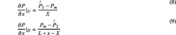 wherein L is a distance from a pressure sensor within a region of the leakage point to a temperature sensor downstream thereof, and the unit is m; S is a distance from a temperature sensor within the region of the leakage point to a pressure sensor downstream thereof, and the unit is m; X is a distance from the location of the leakage point to a pressure sensor upstream within the region of the leakage point, and the unit is m; x represents a gradient direction; P1 is a pressure value detected by the pressure sensor upstream of the leakage point, and the unit is MPa; P2 is a pressure value detected by a pressure sensor downstream of the leakage point, and the unit is MPa; and Pm is the pipeline leakage transient pressure, and the unit is MPa;
it is known from a formula for conservation of momentum within a steam pipeline:
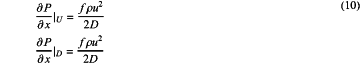 wherein f is a friction coefficient; u is a flow velocity of steam, and the unit is m/s; ρ is a steam density, and the unit is kg/m3; D is a pipeline diameter, and the unit is m; the aperture of a leakage hole is less than the pipeline diameter and a pipeline length, and the variation of friction coefficients of two adjacent sides of the leakage hole within a short distance are ignored;
in the case of pipeline leakage, no phenomena of obvious free outflow and flow reduction of steam occur because of the presence of the thermal insulation layer (6), and therefore pressure gradients upstream and downstream of the leakage point are approximately the same, and after being stabilized, the pressures restore an original pressure distribution along the pipeline;
it can be obtained from simultaneous equations (8)-(10) that:
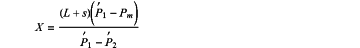 since the arrangement locations of the sensors are known, the location of the leakage point can be positioned accurately according to a calculated value X; and
in step 3, in the process of positioning the location of the leakage point, a correction coefficient ξ is introduced, and the value X is corrected by a method of using temperatures to correct pressures, wherein the correction coefficient is represented by a formula below:
 a corrected new value X is:
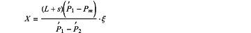 wherein Tm is the pipeline leakage transient steam temperature, and the unit is K; T1 is a temperature value detected by the temperature sensor upstream of the leakage point, and the unit is K; and T2 is a temperature value detected by the temperature sensor downstream of the leakage point, and the unit is K.
|