| CPC G01L 5/1627 (2020.01) | 10 Claims |

|
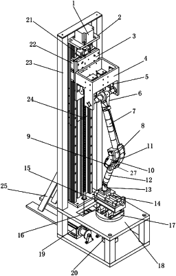
1. A squatting bionic device of a human lower-limb joint, comprising a support, wherein the support comprises a base and a vertical support plate, wherein the vertical support plate is vertically provided on one side of the base; the vertical support plate is provided thereon with a sliding table, wherein the sliding table is driven by a first motor to slide up and down in a height direction of the vertical support plate or to be fixed on the vertical support plate; a horizontal fixed shaft is fixed on the sliding table; the middle of the fixed shaft is connected with a femoral shaft through a first universal joint; a lower end of the femoral shaft is fixedly connected with a lower femur simulation block;
a plantar position adjustment mechanism is provided on the base; a tibial shaft is connected with the plantar position adjustment mechanism through a second universal joint; an upper end of the tibial shaft is connected with an upper tibia simulation block;
an upper end of the upper tibia simulation block is inserted with a meniscus connection block; an upper end of the meniscus connection block is provided with a meniscus clamping slot; a meniscus simulation block is compressed and fixed in the meniscus clamping slot on a top surface of the meniscus connection block;
a lower end of the lower femur simulation block is provided with a circular arc surface in a shape corresponding to a lower end of a human femur; the circular arc surface is supported on the meniscus simulation block; upper femoral ligament clamps are respectively fixed on two sides of the lower femur simulation block; lower femoral ligament clamps are respectively fixed on two sides of the upper tibia simulation block, wherein the lower femoral ligament clamps correspond to the upper femoral ligament clamps; a ligament simulation band is connected between the upper femoral ligament clamps and the lower femoral ligament clamps; a patellar ligament clamp is fixed on the front of the upper tibia simulation block; an upwardly extending patellar ligament simulation band is fixedly connected with the patellar ligament clamp;
a wire rope is wound around a rotation shaft of a second motor, wherein the second motor is fixed on the base; first end of the wire rope is fixed on the rotation shaft of the second motor, and a second end of the wire rope extends upwards, the second end of the wire rope passes around a fixed pulley block, wherein the fixed pulley block is fixed on the sliding table, and the second end of the wire rope is connected with an upper end of the patellar ligament simulation band.
|