| CPC F41G 1/30 (2013.01) | 5 Claims |

|
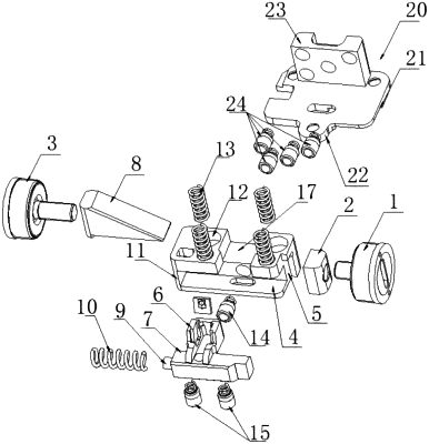
1. An adjustment mechanism comprising a left adjustment screw, a stop block threadedly connected with the left adjustment screw, and a right adjustment screw, wherein the adjustment mechanism further comprises a sliding block provided with a transverse sliding groove at a side surface of a front end of the sliding block, a transverse mounting block having an LED chip module mounting seat mounted at a top portion of a rear end of the transverse mounting block, and a wedge-shaped block;
a right end portion of the transverse mounting block is provided with a limiting pin and a spiral reset spring sleeved on the limiting pin;
the transverse mounting block is assembled in the transverse sliding groove, and the spiral reset spring is placed between the limiting pin and a right stopping plate of the transverse sliding groove;
a left end of the transverse mounting block extends out of the transverse sliding groove and abuts against the stop block;
a bottom surface of the sliding block is provided with an inclined surface portion configured to slide relatively parallel to an inclined surface of the wedge-shaped block;
the right adjustment screw is threadedly connected with a vertical side surface of the wedge-shaped block to push and pull the wedge-shaped block;
a top portion of the sliding block is provided with a mounting groove for mounting the LED chip module mounting seat, and a top surface of the sliding block on either side of the mounting groove is provided with two spring mounting holes which are uniformly arranged and into which vertical spiral springs are assembled respectively;
an extending surface of the mounting groove at a front end thereof is in communication with the transverse sliding groove;
a first spring ejector pin placed below the LED chip module mounting seat is arranged between a rear side surface of the transverse mounting block and a side wall of the transverse sliding groove, and a first steel ball of the first spring ejector pin abuts against the rear side surface of the transverse mounting block;
two second spring ejector pins evenly distributed transversely are provided between a bottom surface of the transverse mounting block and a bottom surface of the transverse sliding groove, and a second steel ball of each of the second spring ejector pins abuts against the bottom surface of the transverse sliding groove.
|