| CPC F41A 21/325 (2013.01) [F41A 21/30 (2013.01); F41A 21/34 (2013.01)] | 17 Claims |

|
1. A mounting assembly for a firearm muzzle device, the mounting assembly comprising:
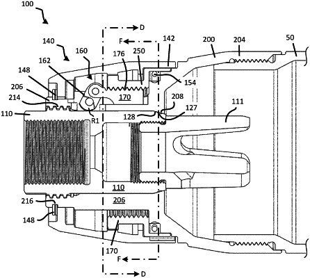
an attachment mount extending along a central axis and having a mount proximal end portion and a mount distal end portion, the mount proximal end portion configured to receive and releasably attach to a muzzle adapter or firearm muzzle;
a locking mechanism on the mount proximal end portion, the locking mechanism having one or more cams received in openings defined in the mount proximal end portion, the one or more cams movable between an engaged position and a disengaged position, wherein in the engaged position, the one or more cams are positioned to engage an outer surface of a muzzle or muzzle adapter installed in the mount proximal end portion; and
a locking nut rotatable about the mount proximal end portion, wherein rotating the locking nut in a first rotational direction moves the cams toward the engaged position and rotating the locking nut in a second rotational direction moves the cams towards the disengaged position,
wherein the locking nut defines threads on an inside surface and the locking mechanism further includes a rack movably connected to each of the one or more cams, the rack having a body on an outside of the mount proximal end portion and defining threads engaging the threads on the inside surface of the locking nut; and
wherein rotating the locking nut about the mount proximal end portion moves each rack axially along the mount proximal end portion, thereby pivoting the one or more cams.
|