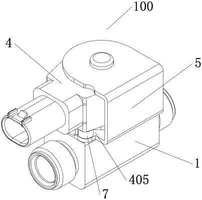
| CPC F16K 31/0655 (2013.01) [F16K 1/36 (2013.01); F16K 1/42 (2013.01); F16K 27/029 (2013.01); F16K 31/0675 (2013.01)] | 10 Claims |

|
1. An electromagnetic valve, comprising a valve body, a coil assembly and a magnetic conductor, wherein at least part of the magnetic conductor is located between the coil assembly and the valve body; wherein the electromagnetic valve comprises a connector, and the connector is configured to connect the magnetic conductor with the valve body; wherein the connector comprises a limiting end portion and a connecting end portion; wherein the coil assembly comprises a main body portion, a connecting portion, an interface portion and a first recess, wherein the connecting portion comprises a first side wall and a second side wall, the first side wall intersects the second side wall, and the interface portion protrudes from the first side wall; wherein the first recess is formed on the connecting portion, the first recess is recessed relative to a lower wall of the connecting portion to form a first opening and is recessed relative to the second side wall of the connecting portion to form a second opening, and the first opening faces an upper wall of the magnetic conductor; wherein the electromagnetic valve has an accommodating portion, wherein a wall forming the accommodating portion comprises an inner wall of the first recess and the upper wall of the magnetic conductor, wherein the coil assembly and the magnetic conductor have at least two relative installation positions, wherein in at least one of the relative installation positions, the limiting end portion of the connector is located in the accommodating portion, and at least part of the connecting end portion of the connector extends into the valve body to be connected to the valve body;
wherein the coil assembly comprises first limiting portion, the magnetic conductor comprises a second limiting portion, and the first limiting portion is located at the second limiting portion;
wherein the magnetic conductor comprises a first plate body, a second plate body and a third plate body, and the third plate body is configured to connect the first plate body with the second plate body, wherein along an axial direction of a first through hole of the main body portion, at least part of the first plate body is located between the valve body and the coil assembly, wherein the coil assembly abuts against a lower wall of the second plate body and an upper wall of the first plate body;
wherein the first plate body comprises a lug portion, and the connector is directed through a hole of the lug portion, wherein at least part of the connecting end portion of the connector is connected with the valve body to fix the lug portion, and the upper wall of the magnetic conductor for forming the accommodating portion is an upper wall of the lug portion;
wherein the first recess comprises a third side wall, wherein along the axial direction of the first through hole, the third side wall is located below the second side wall, wherein the third side wall is closer to the axis of the first through hole than the second side wall, wherein the third side wall is opposite to the second opening, and the third side wall intersects with the first side wall; wherein the main body portion comprises a first base portion, and a wall forming the first base portion comprises the first side wall, the third side wall and the lower wall of the connecting portion; and
wherein the first limiting portion is formed as a protrusion, the second limiting portion is formed as a recess, and the first limiting portion is formed on the first base portion, wherein along the axial direction of the first through hole, the first limiting portion protrudes toward the first plate body from a lower wall of the first base portion; wherein the second limiting portion is formed on the first plate body, and the second limiting portion is recessed relative to the upper wall of the first plate body, wherein the second limiting portion has an opening on an upper surface of the first plate body, and a wall forming the second limiting portion comprises a wall of the lug portion.
|