| CPC F03B 17/065 (2013.01) [H02K 7/1004 (2013.01); H02K 7/1823 (2013.01); H02K 49/102 (2013.01)] | 14 Claims |

|
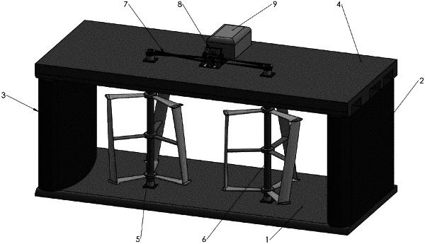
1. A twin-turbine hydrokinetic energy system comprising:
a turbine frame comprising:
a top portion,
a bottom portion opposite the top portion, and
two sidewalls perpendicular to the bottom portion, the two sidewalls each comprising a single continuously curved convex surface, each of the single continuously curved convex surfaces facing inwardly towards two counter-rotating vertical turbine rotors and comprising an apex extending inwardly towards the two counter-rotating vertical turbine rotors to accelerate water through the turbine frame on an upstream side of the turbine frame and decelerate water on a downstream side of the turbine frame, wherein each particular sidewall comprises a unitary body of varying thickness with a point of maximum thickness corresponding to the apex of the particular sidewall;
the two counter-rotating vertical turbine rotors housed within the turbine frame, wherein the two counter-rotating vertical turbine rotors are positioned within the turbine frame along a plane between the apex of each of the two sidewalls, each turbine rotor having a low solidity and comprising:
a shaft connected to at least the top portion of the turbine frame;
a top hub proximate a top portion of the shaft, the top hub hosting three upper arms;
a bottom hub proximate a bottom portion of the shaft, the bottom hub hosting three lower arms; and
three blades, wherein each blade is connected to an upper arm of the three upper arms and a lower arm of the three lower arms; and
a single power take-off shaft that couples the two turbine rotors to a generator such that torque and rotational speed of the two turbine rotors is converted into power via the generator;
wherein the unitary body of each sidewall comprises a single linear surface opposite the continuously curved convex surface and wherein both the single continuously curved convex surface and the single linear surface of each sidewall extend from a mouth of the turbine frame to an exit of the turbine frame.
|