| CPC F01N 3/2026 (2013.01) [F01N 3/2828 (2013.01); F01N 2240/16 (2013.01); F01N 2330/04 (2013.01)] | 14 Claims |

|
1. A device for the aftertreatment of exhaust gases from an emission source, comprising
an exhaust tract through which an exhaust gas can flow in a direction of flow, with at least one catalytic converter, the catalytic converter having:
a ceramic honeycomb body (1, 5, 8, 12, 15) having:
a catalytically active surface coating,
an electrically heatable resistance heater (3, 7, 9), the heater (3, 7, 9) having a metallic electrical conductor (3, 7, 9),
a plurality of flow channels which can be flowed through from a gas inlet side (11, 16) to a gas outlet side,
wherein the conductor (3, 7, 9) is integrated in the ceramic honeycomb body (1, 5, 8, 12, 15) in which the exhaust gases flow, and is arranged downstream of the gas inlet side (11, 16) and upstream of the gas outlet side, as viewed in the direction of flow,
wherein the conductor is arranged in a plurality of clearances (17) in the ceramic honeycomb body (1, 5, 8, 12, 15) in which the exhaust gases flow downstream of an upstream end face of the gas inlet side (16) and/or upstream of a downstream end face of the gas outlet side,
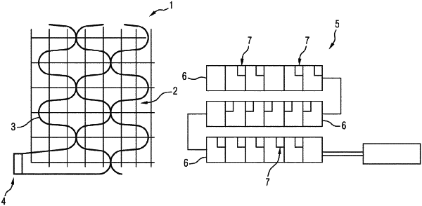
wherein the conductor (3, 7, 9) is integrated in the plurality of clearances so that each portion of the conductor (3, 7, 9) in each of the clearances is circumferentially surrounded on a radial internal and a radial external side by the ceramic honeycomb body and in contact with the ceramic honeycomb body on an axial side, wherein the ceramic honeycomb body (5) is formed from at least two honeycomb bodies configured as disk elements (6), which are arranged one after the other in the direction of flow, each of the disk elements (6) having a plurality of clearances with an integrated conductor (7), with the conductors (7) in the disk elements forming a common conductor that extends axially through the honeycomb body.
|