| CPC C02F 1/025 (2013.01) [B01D 53/72 (2013.01); B01D 53/86 (2013.01); B01F 27/17 (2022.01); C02F 1/02 (2013.01); C02F 11/00 (2013.01); C02F 11/10 (2013.01); B01F 2101/305 (2022.01); C02F 2103/32 (2013.01); C02F 2201/002 (2013.01)] | 5 Claims |

|
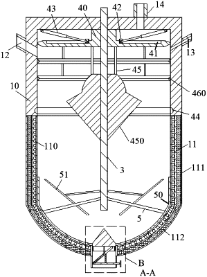
1. A kitchen waste wastewater treatment equipment, comprising a reaction kettle, wherein the reaction kettle comprises a top cover barrel and a heating barrel fixedly connected with a bottom of the top cover barrel, a lower end of the heating barrel is arc-shaped, and the heating barrel comprises a heating layer, a shell and a heat preservation layer filled between the heating layer and the shell;
a side wall of an upper end of the reaction kettle is provided with a liquid inlet and a vacuum pumping port, the liquid inlet and the vacuum pumping port are symmetrically arranged about an axis of the reaction kettle, a hydrolysis gas outlet is formed in a top of the reaction kettle, and a discharging outlet is formed in a bottom of the reaction kettle;
a discharging mechanism is arranged on the discharging outlet, a driving shaft concentric with the top cover barrel is rotatably connected to the top cover barrel, a pressurizing mechanism is arranged at a position, close to an upper end, of a side wall of the driving shaft, and a stirring mechanism is arranged at a position, close to a lower end, of the side wall of the driving shaft;
the pressurizing mechanism comprises a pressurizing disk sleeved on the driving shaft and connected to the driving shaft in a threaded fit manner, limiting grooves evenly distributed in a circumferential direction of the pressurizing disk are formed in a top of the pressurizing disk, a moving seat is slidably connected in one of the limiting grooves, a telescopic rod is hinged between the moving seat and the top of an inner wall of the reaction kettle, an exhaust ring groove is formed in an inner wall of the top cover barrel, and an auxiliary discharging group is installed at a lower end of the pressurizing disk;
the discharging mechanism comprises a conical blocking cone, slidably connected in the discharging outlet in an up-down sliding manner, with its top gradually reduced in diameter upwards, a conical portion at an upper end of the blocking cone is inserted into the reaction kettle, a lower end of the blocking cone blocks the discharging outlet, an annular cylinder is installed on a lower end face of the blocking cone, filtering holes evenly distributed are formed in a side wall of the annular cylinder, and a discharging driving group for driving the blocking cone to move up and down is arranged on the discharging outlet; and
the discharging driving group comprises a fixing rod fixedly connected to a middle of the discharging outlet, vertical rods symmetrically arranged in an axial direction of the fixing rod are fixedly connected to the fixing rod, a lower end of the blocking cone is provided with a spring groove, one of the vertical rods is inserted into the spring groove and is connected to the spring groove through a reset spring, an inclined ejector rod is rotatably connected to a middle of the fixing rod, an upper end of the ejector rod is inserted into the annular cylinder and receives the blocking cone, a guide groove is formed in an end, located below the fixing rod, of the ejector rod, a connecting shaft is slidably connected in the guide groove, a pull rod is rotatably sleeved on the connecting shaft, a supporting rod is installed at a top of the pull rod, and a top of the supporting rod is used for bearing a portion, located on an upper side of the fixing rod, of the ejector rod.
|