| CPC B60N 2/065 (2013.01) [B60N 2/06 (2013.01); B60N 2/0705 (2013.01); B60N 2/20 (2013.01); B60N 2/30 (2013.01); B60N 2/12 (2013.01)] | 20 Claims |

|
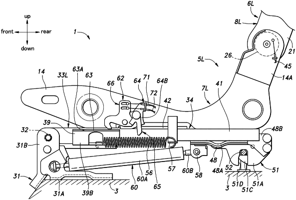
1. A vehicle seat including a seat cushion, wherein the vehicle seat is capable of taking a usable position and a stowed position in which the seat cushion is rotatably lifted away from a floor, the vehicle seat comprising:
a support member coupled to the floor;
a rotating member rotatably supported by the support member via a support shaft extending in a right-left direction;
a lower rail extending in a front-rear direction and coupled to the rotating member;
an upper rail slidably supported by the lower rail and coupled to the seat cushion;
a coupling device provided at a rear end of the lower rail and capable of selectably connecting to a striker provided on the floor; and
an urging device extending the front-rear direction and having a front end coupled to the support member and a rear end coupled to the lower rail,
wherein the urging device is configured to be expandable and contractible in a longitudinal direction thereof so as to urge the seat cushion in such a direction as to rotate about the support shaft away from the floor, and
wherein the front end of the urging device is arranged lower than an upper end of the striker.
|