| CPC B01F 27/1132 (2022.01) [B01F 27/808 (2022.01)] | 20 Claims |

|
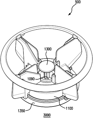
1. A guard for an impeller having at least a first blade and a second blade, each of the first and second blades having front and rear blade faces, an upper edge, an outer edge, an upper outer corner where the upper edge contacts the outer edge, a lower edge, and an inner edge, the guard comprising:
(A) an upper annular ring having an upper annular ring horizontal axis and a first internal diameter, the upper annular ring having an upper surface and a lower surface, wherein the upper surface further comprises a peripheral edge having a rounded surface and wherein the lower surface includes at least a first blade receiving groove for receiving the upper outer corner of the first blade, the first blade receiving groove having first and second sides; and a second blade receiving groove for receiving the upper outer corner of the second blade, the second blade receiving groove having first and second sides;
(B) a lower annular ring having a lower annular ring horizontal axis and a second internal diameter, wherein the second internal diameter is smaller than the first internal diameter;
(C) at least a first brace member and a second brace member, each attached to the upper annular ring and the lower annular ring, each of the first brace member and second brace member being vertically arranged between the upper annular ring and the lower annular ring perpendicular to the upper annular ring horizontal axis and the lower annular ring horizontal axis,
(1) the first brace member having a first brace member front wall, a first brace member rear wall, a first brace member outer side wall, and a first brace member inner side wall contacting the lower annular ring, the first brace member front wall or the first brace member rear wall being arranged to face a front or rear blade face of the first blade and forming the second side of the first blade receiving groove;
(a) the first brace member having a vertical slot for receiving a portion of an inner edge of the first blade, and a catch for lockably receiving a portion of the lower edge of the first blade;
(2) the second brace member having a second brace member front wall, a second brace member rear wall, a second brace member outer side wall and a second brace member inner side wall contacting the lower annular ring, the second brace member front wall or the second brace member rear wall being arranged to face a front or rear blade face of the second blade and forming the second side of the second blade receiving groove;
(b) the second brace member having a vertical slot for receiving a portion of an inner edge of the second blade, and a catch for lockably receiving a portion of the lower edge of the second blade.
|