| CPC B01D 46/0031 (2013.01) [B01D 46/0001 (2013.01); B01D 46/10 (2013.01); B64G 1/48 (2013.01); B01D 2265/06 (2013.01)] | 10 Claims |

|
1. A phase separator comprising:
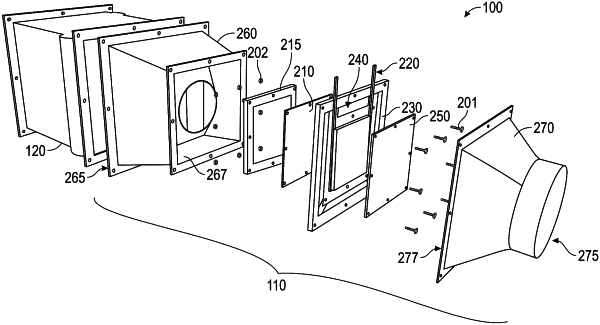
an inlet of an inlet duct, the inlet configured to receive two-phase flow from a two-phase flow source that is in line with the inlet duct, wherein the two-phase flow includes gas and liquid;
a liquid permeable membrane arranged at an outlet of the inlet duct, the liquid permeable membrane configured to pass the liquid for capture while diverting the gas to result in an annular flow of the gas around the liquid permeable membrane;
an outlet of an outlet duct configured to output the annular flow of the gas that is separated from the liquid;
a membrane frame, wherein the liquid permeable membrane is arranged in a central portion of the membrane frame;
a liquid recovery loop arranged on an opposite side of the membrane frame from the liquid permeable membrane and configured to capture the liquid passed through the liquid permeable membrane;
a backplate separating the liquid recovery loop from an inlet of the outlet duct; and
a membrane retainer separating the liquid permeable membrane from an outlet of the inlet duct, wherein the backplate is affixed to the membrane retainer through the membrane frame.
|