| CPC H05B 45/3578 (2020.01) [H05B 45/355 (2020.01); H05B 45/3725 (2020.01)] | 8 Claims |
|
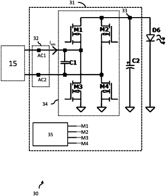
1. A LED driver for generating an output power for driving an LED load from a power source adapted to provide an alternating input current, the LED driver comprising:
an input arrangement comprising a first terminal and a second terminal, for receiving the alternating input current from the power source;
an output node for providing an output power for driving the LED load;
a capacitor connected between the output node and a ground/reference voltage, wherein the capacitor is configured so that, when the LED driver is powered, a voltage across the capacitor is substantially constant;
a switching arrangement comprising:
a first switch directly connecting the first terminal to the output node;
a second switch directly connecting the second terminal to the output node;
a third switch directly connecting the first terminal to the ground/reference voltage; and
a fourth switch directly connecting the second terminal to the ground/reference voltage, wherein the switching arrangement is adapted to controllably connect the first terminal to either the output node or the ground/reference voltage and the second terminal to either the output node or the ground/reference voltage to thereby enable control of a magnitude and phase, relative to a phase of the alternating input current, of the voltage between the first and second terminals; and
a controller adapted to control the switching arrangement to thereby control the magnitude of voltage between the first and second terminals and the phase of the voltage between the first and second terminals relative to a phase of the alternating input current, so that energy transfer between the input arrangement and the output node is bi-directionally controllable to thereby control an average magnitude of the output power,
wherein the controller is adapted to control the frequency of the voltage between the first and the second terminals to be equal to the frequency of the alternating input current,
wherein the controller is adapted to be operable in:
a first mode, in which the controller allows current to flow through the first switch and the fourth switch, and prevents current from flowing through the second switch and the third switch, so that the voltage between the first and second terminals is equal in magnitude and polarity to the voltage across the capacitor;
a second mode, in which the controller allows current to flow through the second switch and the third switch, and prevents current from flowing through the second switch and the fourth switch, so that the voltage between the first and second terminals is equal in magnitude but opposite in polarity to the voltage across the capacitor; and
a third mode, in which the controller controls the switching arrangement so that the first and second terminals are effectively short-circuited together,
wherein the controller is adapted to that the cumulative time that the controller operates in the first or second mode is between 1 and 9 times the cumulative time that the controller operates in the third mode, and preferably between 2.8 and 3.6 times the cumulative time that the controller operates in the third mode.
|