| CPC H02J 9/061 (2013.01) [H02J 7/00309 (2020.01); H02J 7/00306 (2020.01)] | 20 Claims |

|
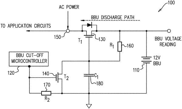
1. A battery backup unit (BBU) cut-off and recharge circuit comprising:
a mechanical relay switch with self-latch capability;
a power entry connection connected to a main power supply, wherein power from said power entry connection flows to application circuits for an electronic device, and said mechanical relay switch with said self-latch capability is positioned between a BBU and said power entry connection; and
a microcontroller, wherein said microcontroller is operative to:
detect a loss of power from said main power supply,
open said mechanical relay switch with said self-latch capability to enable said BBU to discharge through said power entry connection to said application circuits,
detect a status of charge (SOC) for said BBU, and
upon detecting that said SOC is under a predefined threshold, set said BBU cut-off and recharge circuit to a lockdown state by closing said mechanical relay switch with said self-latch capability.
|