| CPC H01G 9/048 (2013.01) [H01G 9/0032 (2013.01); H01G 9/08 (2013.01); H01G 9/145 (2013.01); H01G 9/008 (2013.01)] | 14 Claims |

|
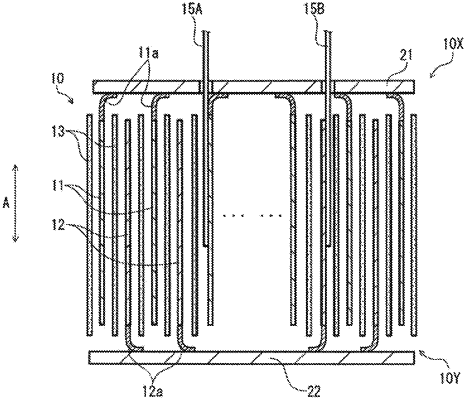
1. An electrolytic capacitor comprising:
a capacitor element including:
a wound body in which a first electrode foil and a second electrode foil are wound, the first electrode foil and the second electrode foil facing each other;
a first lead terminal connected to the first electrode foil; and
a second lead terminal connected to the second electrode foil;
a first current collector connected to the first electrode foil; and
a case that houses the capacitor element and the first current collector, wherein:
the first electrode foil includes a first facing portion that faces the second electrode foil and a first non-facing portion that does not face the second electrode foil, the first non-facing portion being located at a first end portion in a winding axis of the wound body,
the first current collector is disposed in a vicinity of the first end portion of the wound body to be connected to the first non-facing portion of the first electrode foil, and
the first current collector includes an opening, and the second lead terminal is inserted in the opening.
|