| CPC H01F 27/025 (2013.01) [H01F 27/105 (2013.01)] | 13 Claims |

|
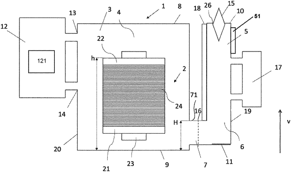
1. A static electric induction arrangement comprising:
a static electric induction device tank comprising a top part, a bottom part and at least one wall extending between the top part and the bottom part, which is for accommodating a dielectric fluid;
an accessory;
an accessory tank comprising a top part, a bottom part and at least one wall extending between the top part and the bottom part, which is for accommodating the dielectric fluid, the accessory tank further comprising at least one opening arranged in the top part of the accessory tank to receive the accessory therein;
a fluid connection part for accommodating the dielectric fluid;
a heat exchanger for accommodating the dielectric fluid;
an outlet for accommodating the dielectric fluid; and
an inlet for accommodating the dielectric fluid;
a static electric induction device arranged in the static electric induction device tank,
wherein the static electric induction device tank is in fluid connection with the accessory tank via the fluid connection part,
wherein an upper portion of the fluid connection part, with respect to the bottom part of the static electric induction device tank in a vertical direction of the static electric induction arrangement, is located at a first height,
wherein the heat exchanger is in fluid connection with the static electric induction device tank via the outlet and the inlet,
wherein the outlet is arranged to lead the dielectric fluid from the static electric induction device tank to the heat exchanger,
wherein the inlet is arranged to return the dielectric fluid from the heat exchanger to the static electric induction device tank,
wherein a top part of a section of the inlet adjacent to the static electric induction device tank, with respect to the bottom part of the static electric induction device tank in the vertical direction, is located at a second height the same as or larger than the first height,
wherein a top part of a section of the outlet adjacent to the static electric induction device tank, with respect to the bottom part of the static electric induction device tank in the vertical direction, is located at a third height larger than the second height,
wherein the top part of the static electric induction device tank, with respect to the bottom part of the static electric induction device tank in the vertical direction, is located at a fourth height larger than the third height,
wherein a top part of the heat exchanger, with respect to the bottom part of the static electric induction device tank in the vertical direction, is located at a fifth height larger than the fourth height, and
wherein the static electric induction device comprises an insulation material, wherein the insulation material, with respect to the bottom part of the static electric induction device tank in the vertical direction, is located at a sixth height, and wherein the at least one opening, with respect to the bottom part of the static electric induction device tank in the vertical direction, is located at a seventh height larger than the sixth height.
|