| CPC G01N 1/16 (2013.01) [G01N 1/12 (2013.01); G01N 2001/1031 (2013.01)] | 9 Claims |

|
1. A sampling device for geological fluid detection, comprising:
a support frame (1) having an L-shaped structure with an upper portion and a bottom portion;
a second support plate (106) is arranged at the upper portion of the support frame (1);
a protective cover (2), the protective cover (2) is mounted at the bottom portion of the support frame (1);
fixing members (3), wherein the fixing members (3) are mounted above at the bottom portion of the support frame (1), and there are two fixing members (3) with a connecting plate (301) between the two fixing members (3);
a locking inclined block (4), the locking inclined block (4) is mounted at the bottom portion of the support frame (1);
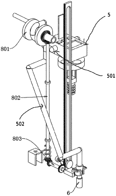
a detector (5), the detector (5) is provided with a water inlet pipe (501), and the detector (5) is clamped to the second support plate (106) of the support frame (1);
a mounting sleeve (6), the mounting sleeve (6) is clamped to a bottom of the upper portion of the support frame (1), a fluid drainage tube (502) is mounted between the water inlet pipe (501) of the detector (5) and the mounting sleeve (6), a test strip (503) is mounted above the detector (5) for double detection of the fluid through the detector (5) and the test strip (503);
a positioning seat (7), the positioning seat (7) is bolted to the bottom of the upper portion of the support frame (1);
a drive mechanism (8), the drive mechanism (8) consists of a winding wheel (801), a first rotation shaft (802), a second rotation shaft (803), a lifting frame (804) and a mounting block (80401) together, a bevel gear disk (806) is mounted on a side of the winding wheel (801), and the bevel gear disk (806) is driven to rotate when the winding wheel (801) rotates, and a portion of the fluid drainage tube (502) is wound around the winding wheel (801), the winding wheel (801) is mounted to the support frame (1), and two first bevel gears (808A, 808B) are mounted respectively at both ends of the first rotation shaft (802), and one of the two first bevel gears (808A) at an upper end of the first rotation shaft (802) engages with the bevel gear disk (806), so that the first rotation shaft (802) will be driven to rotate when the winding wheel (801) rotates, and a second bevel gear (810) is mounted at one end of the second rotation shaft (803), and the second bevel gear (810) engages with the other one of the two first bevel gears (808B) at a lower end of the first rotation shaft (802), so that the second rotation shaft (803) will be driven to rotate when the first rotation shaft (802) rotates, and a toggle gear (812) is mounted at an another end of the second rotation shaft (803), and the toggle gear (812) will be driven to rotate when the second rotation shaft (803) rotates, and the lifting frame (804) has a rack (814) on one side, and the rack (814) engages with the toggle gear (812), and the lifting frame (804) will be pushed up and down when the toggle gear (812) rotates, the mounting sleeve (6) has an annular groove (606), the mounting block (80401) is clamped in the annular groove (606) of the mounting sleeve (6), the mounting block (80401) will be driven to move when the lifting frame (8044) moves, so that the mounting sleeve (6) will be driven by the mounting block (80401) to move, and a position of the mounting sleeve (6) will be adjusted;
a loading tray (9), the loading tray (9) is mounted to the support frame (1); and
a sampling test tube (10), the sampling test tube (10) is arranged in the loading tray (9).
|