| CPC G01C 19/5712 (2013.01) [G01C 19/5776 (2013.01)] | 20 Claims |
|
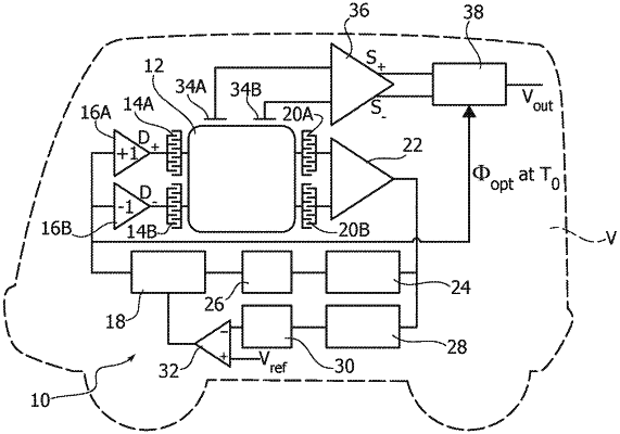
1. A circuit comprising:
an inertial measurement unit configured to be oscillated via a driving signal provided by driving circuitry;
a lock-in amplifier configured to:
receive a sensing signal from the inertial measurement unit and a reference demodulation signal which is a function of the driving signal; and
provide an inertial measurement signal based on the sensing signal, wherein the reference demodulation signal is affected by a variable phase error;
phase meter circuitry configured to:
receive the driving signal and the sensing signal; and
provide, as a function of a phase difference between the driving signal and the sensing signal, a phase correction signal for the reference demodulation signal; and
a correction node configured to apply the phase correction signal to the reference demodulation signal so that, in response to the phase correction signal being applied to the reference demodulation signal, the phase error is maintained in a vicinity of a reference value.
|