| CPC F23R 3/286 (2013.01) [F02C 3/14 (2013.01); F23R 3/346 (2013.01); F23R 3/42 (2013.01); F23R 3/58 (2013.01); F02C 7/22 (2013.01); F23R 3/12 (2013.01); F23R 3/34 (2013.01); F23R 2900/00015 (2013.01)] | 19 Claims |

|
1. A combustor assembly, the combustor assembly comprising:
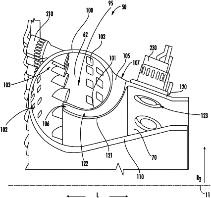
a volute wall extended annularly around a combustor centerline, and wherein the volute wall is extended at least partially as a spiral curve from a circumferential reference line around the combustor centerline such that a portion of the volute wall curves from a first radially outer location to a first radially inward location, the first radially inward location located forward of the first radially outer location, and wherein the volute wall defines an annular volute combustion chamber therewithin;
an annular inner wall extended at least partially along a lengthwise direction from the volute wall;
an annular outer wall extended at least partially along the lengthwise direction from the volute wall, wherein the annular inner wall and the annular outer wall are separated along a radial direction from the combustor centerline and a portion of the annular outer wall curves from a second radially outer location to a second radially inward location, the second radially inward location located forward of the second radially outer location, and wherein a primary flow passage is defined between the annular inner wall and the annular outer wall in fluid communication with the annular volute combustion chamber, the annular volute combustion chamber being radially outward of the primary flow passage relative to the combustor centerline;
at least one secondary flow passage defined by the portion of the volute wall and the portion of the annular outer wall, the at least one secondary flow passage having:
a secondary inlet opening defined through the annular outer wall at the second radially outer location of the annular outer wall and at the first radially outer location of the portion of the volute wall; and
a secondary outlet opening adjacent to and in fluid communication with the annular volute combustion chamber, the secondary outlet opening defined by the first radially inward location of the portion of the volute wall and the second radially inward location of the portion of the annular outer wall, the secondary outlet opening located axially forward of and radially inward of the secondary inlet opening such that a flow of fluid is introduced into the annular volute combustion chamber in a direction that is radially inward and forward of the annular volute combustion chamber,
wherein the volute wall extends from a first location disposed at the secondary outlet opening to a second location disposed at the annular inner wall.
|