| CPC F21V 5/007 (2013.01) [F21V 5/008 (2013.01); G02B 19/0009 (2013.01); G02B 19/0066 (2013.01); F21Y 2115/10 (2016.08)] | 9 Claims |

|
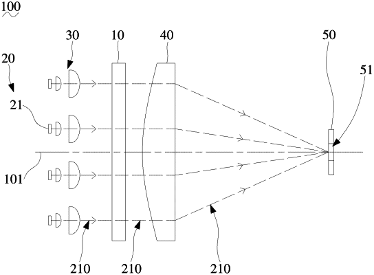
1. A light source system, comprising:
an array of light-emitting diodes, wherein the light-emitting diodes comprise light-emitting diode chips;
a collimating lens group located on a light path of light emitted by the array of the light-emitting diodes, wherein the collimating lens group is configured to collimate light beams emitted by the light-emitting diode chips; and
a fly-eye lens arranged on a light path of light outputted from the collimating lens group, wherein the fly-eye lens comprises micro lens units corresponding to the light-emitting diode chips,
wherein for at least one light-emitting diode chip of the light-emitting diode chips, an image formed by each of the at least one light-emitting diode chip on surfaces of the micro lens units is completely within a surface of one of the micro lens units, and
wherein the fly-eye lens comprises a front fly-eye lens sub-unit and a back fly-eye lens sub-unit, wherein the back fly-eye lens subunit is located at a focal plane of the front fly-eye lens sub-unit.
|