| CPC E03C 1/2665 (2013.01) [B02C 18/0084 (2013.01); B02C 18/0092 (2013.01); B09B 3/32 (2022.01); B09B 3/35 (2022.01); B09B 2101/70 (2022.01)] | 10 Claims |

|
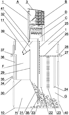
1. A centralized treatment device for kitchen waste, comprising:
an upper box, with a horizontal sieve plate fixed inside, provided with a smashing area and a gas treatment area located above the horizontal sieve plate, and a waste pretreatment area and a gas circulation area located below the horizontal sieve plate; wherein the gas circulation area is connected with the gas treatment area through sieve holes of the horizontal sieve plate, and the gas treatment area is filled with activated carbon;
an outer cover hinged to a top end of the upper box and configured to cover upper openings of the smashing area and the gas treatment area and open the upper openings of the smashing area and the gas treatment area when the outer cover is turned upward;
a pulverizer located in the smashing area, wherein an inlet of the pulverizer faces upward, and an outlet of the pulverizer is connected with a top end of an upper loading channel of the waste pretreatment area through the sieve holes of the horizontal sieve plate;
an inner cover hinged in the smashing area and located above the pulverizer and configured to bear or dump organic waste;
a filter press mounted in the waste pretreatment area, wherein an inlet of the filter press is connected with a bottom end of the upper loading channel, a liquid outlet of the filter press is connected with a downcomer, a filtrate outlet of the filter press is connected with the downcomer, and a filter residue outlet of the filter press is connected with a top opening of a lower loading channel;
a drying granulator mounted in the waste pretreatment area, wherein an inlet of the drying granulator is connected with a bottom end of the lower loading channel, and an outlet of the drying granulator is connected with a bottom end of the waste pretreatment area;
a lower box internally provided with a reservoir area located on a left side for accommodating an acidic solution and a degradation area located on a right side, wherein a separation area located on a left side of the degradation area is arranged below the reservoir area; an upper end of the reservoir area and a bottom end of the gas circulation area are both connected with an upper end of the degradation area, and a lower end of the degradation area is connected with a lower end of the reservoir area; the downcomer extends to a bottom end of the separation area and is connected with the bottom end of the separation area; and a bottom end of the upper box is fixedly connected with a top end of the lower box;
an electrolysis device provided in the degradation area and configured to decompose organic matter in water;
a hanging basket hinged in the reservoir area and configured to receive solid residue particles falling from a bottom of the waste pretreatment area, wherein a plurality of through holes are provided between an inner wall and an outer wall of the hanging basket;
a material box fixedly mounted in the waste pretreatment area and configured to store a powder treatment agent, wherein a fan blade configured to allow the power treatment agent to flow out from a discharge outlet of the material box is hinged in the material box, and the discharge outlet of the material box is located directly above the top opening of the lower loading channel;
an exhaust fan, one end of which is connected with a top end of the gas treatment area, and an other end of which is connected with the outside; and
a linkage mechanism including a first transmission rope, a second transmission rope, and a transmission rod, wherein two ends of the first transmission rope are fixedly connected with the outer cover and the hanging basket respectively, two ends of the second transmission rope are fixedly connected with the outer cover and the inner cover respectively, and two ends of the transmission rod are hinged to the outer cover and the fan blade respectively; and when the outer cover blocks the upper opening of the smashing area, the hanging basket, the inner cover, and the fan blade are all inclined downwardly from right to left.
|