| CPC B60T 13/741 (2013.01) [B60T 1/065 (2013.01); F16D 55/226 (2013.01); F16D 65/0056 (2013.01); F16D 65/0075 (2013.01); F16D 65/18 (2013.01); F16D 2055/002 (2013.01); F16D 2055/0016 (2013.01); F16D 2121/26 (2013.01)] | 17 Claims |

|
1. A caliper body of a disc brake caliper of the floating type, wherein said caliper body is adapted to be arranged straddling a brake disc having first and second opposite braking surfaces adapted to rotate about a rotation axis (X-X) defining an axial direction (A-A), radial directions (R-R) orthogonal to said axial direction (A-A) and passing through said rotation axis (X-X), a circumferential direction (C-C) orthogonal to each of said radial directions (R-R) and to said axial direction (A-A), and, in a specific point, a tangential direction (T-T) orthogonal to the axial (A-A) and radial (R-R) directions passing through said specific point, wherein:
said caliper body comprises a bracket adapted to connect to a caliper support provided in a vehicle;
said caliper body comprises a floating element slidingly supported by said bracket so as to move relative to the bracket along said axial direction (A-A);
said floating element comprises a first floating element portion adapted to face said first braking surface either directly or indirectly;
said first floating element portion comprises at least one biasing device housing adapted to accommodate a biasing device capable of applying a biasing force to a first brake pad facing said first braking surface to apply a braking action on said brake disc;
said floating element comprises at least one first floating element bridge supported by said first floating element portion and protruding straddling said brake disc;
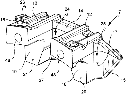
said floating element comprises a plate-shaped portion overhangingly supported by said at least one first floating element bridge which extends with a first outer plate-shaped portion side thereof, arranged opposite to said biasing device, on a plane extending along circumferential (C-C) and radial (R-R) directions;
wherein
said plate-shaped portion comprises plate-shaped portion end portions overhangingly protruding from opposite sides and in circumferential direction (C-C) with respect to said at least one first floating element bridge;
said plate-shaped portion comprises a second inner plate-shaped portion side facing said biasing device and opposite said first outer plate-shaped portion side;
said plate-shaped portion comprises at least two plate-shaped portion projections overhangingly protruding from said second inner plate-shaped portion side;
said at least two plate-shaped portion projections comprise thrust surfaces adapted to bias a second brake pad against said second braking surface;
said at least two plate-shaped portion projections, mutually, and with said plate-shaped portion, form a plate-shaped portion ventilation channel mainly extending in radial direction (R-R),
wherein said plate-shaped portion comprises a plate-shaped inner surface configured to axially face the second brake pad, said plate-shaped inner surface continuously extends the height of the channel in the radial direction (R-R) between the at least two plate-shaped portion projections.
|