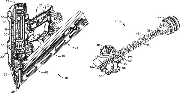
| CPC B25C 1/008 (2013.01) [B25C 1/06 (2013.01)] | 14 Claims |

|
1. A driver machine for use in a fastener driving tool, said driver machine comprising:
(a) a hollow cylinder having a movable piston therewithin;
(b) a guide body that is sized and shaped to receive a fastener that is to be driven;
(c) an elongated driver that is in mechanical communication with said piston at least during a driving stroke, said driver being sized and shaped to push said fastener from an exit portion of said guide body, said driver extending from a first end to a second end and having an elongated face therebetween, said first end being proximal to said piston, said second end being distal from said piston and making contact with said fastener during said driving stroke, said driver exhibiting a plurality of protrusions at first predetermined locations in a first surface of the driver; said driver having a plurality of through-holes in a second surface of the driver at second predetermined locations, in which each of said plurality of through-holes exhibits a predetermined size and shape;
(d) a movable lifter that moves said driver toward a ready position during a return stroke, by mechanically engaging with said plurality of protrusions of the driver; and
(e) a movable latch that is biased so that a first portion of the latch mechanically engages against said second surface of the driver at least during said return stroke;
(f) wherein:
(i) after said driving stroke, when said driver has stopped its movement at a location that is within at least one predetermined “in specification” position, then said biased latch is operable to move such that said first portion of the latch is moved into one of said plurality of through-holes in said driver, before initiation of said return stroke; and
(ii) after said driving stroke, when said driver has stopped its movement at a location that is not within said at least one predetermined “in specification” position, then said first portion of the latch cannot move into one of said plurality of through-holes in said driver;
in which said latch includes a second portion that is to be used for determining a position of the latch; and
further comprising:
(g) a sensor mounted proximal to said second portion of the latch, so as to detect whether or not the biased latch has moved, after said driving stroke; and
(h) a system controller comprising: (i) a processing circuit, (ii) a memory circuit including instructions executable by said processing circuit, (iii) an input/output interface (I/O) circuit, said I/O circuit being in communication with said sensor so that an output signal produced by said sensor is signal-conditioned as a latch position signal when received at said processing circuit;
(i) wherein: said system controller is operable to detect a position of said latch after said driving stroke, based upon a status of said latch position signal; and:
(i) when the first portion of the latch is moved into one of said plurality of through-holes in said driver, then said sensor will detect said second portion of the latch, and said return stroke will be permitted by the system controller to occur; and
(ii) when the first portion is not moved into one of said plurality of through-holes in said driver, then said sensor will not detect said second portion of the latch, and said return stroke will be prevented by the system controller from occurring.
|