| CPC A61H 1/0222 (2013.01) [A61F 5/04 (2013.01); A61F 5/042 (2013.01); A61F 5/048 (2013.01); A61G 7/05 (2013.01); A61G 7/072 (2013.01); A61G 13/009 (2013.01); A61G 13/04 (2013.01); A61G 13/121 (2013.01); A61G 13/1295 (2013.01); A61H 1/0296 (2013.01); A61G 7/012 (2013.01); A61G 13/06 (2013.01); A61H 2201/5007 (2013.01); A61H 2203/0468 (2013.01); A61H 2205/04 (2013.01)] | 8 Claims |

|
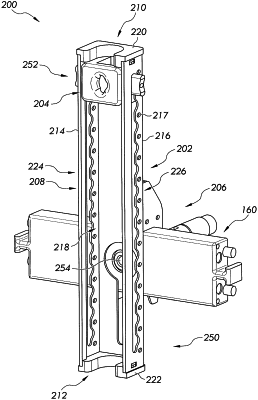
1. A cervical traction assembly for use with a patient support apparatus, the cervical traction assembly comprising:
an adjustment carriage track member that mounts to a mount support member of a forward column assembly of the patient support apparatus, the adjustment carriage track member comprising a connecting bracket assembly that releasably connects to the mount support member, the adjustment carriage track member comprising a track body comprising a pair of opposing sidewalls that are spaced-apart from each other to define an elongated channel therebetween, each sidewall including a guide track that extends along a length of the respective sidewall; and
a rope angle adjustment carriage that is located within the elongated channel, the rope angle adjustment carriage comprising a first track engagement member received by one of the guide tracks of one of the sidewalls and a second track engagement member received by another of the guide tracks of another of the sidewalls;
wherein the first track engagement member has a locked configuration that inhibits movement of the rope angle adjustment carriage along the elongated channel and an unlocked configuration that allows movement of the rope angle adjustment carriage along the elongated channel.
|