| CPC A61B 5/1459 (2013.01) [A61B 1/00006 (2013.01); A61B 1/00016 (2013.01); A61B 1/00032 (2013.01); A61B 1/00052 (2013.01); A61B 1/00087 (2013.01); A61B 1/00105 (2013.01); A61B 1/00108 (2013.01); A61B 1/00126 (2013.01); A61B 1/00154 (2013.01); A61B 1/00181 (2013.01); A61B 1/313 (2013.01); A61B 5/0004 (2013.01); A61B 5/0015 (2013.01); A61B 5/0205 (2013.01); A61B 5/14551 (2013.01); A61B 5/14552 (2013.01); A61B 5/7225 (2013.01); A61B 5/7278 (2013.01); A61B 5/742 (2013.01); A61B 1/0005 (2013.01); A61B 1/00142 (2013.01); A61B 5/0071 (2013.01); A61B 5/1495 (2013.01); A61B 5/14546 (2013.01); A61B 5/6852 (2013.01); A61B 5/7445 (2013.01); A61B 2505/05 (2013.01); A61B 2560/0214 (2013.01); A61B 2560/0223 (2013.01); A61B 2560/0443 (2013.01)] | 29 Claims |

|
1. A device comprising:
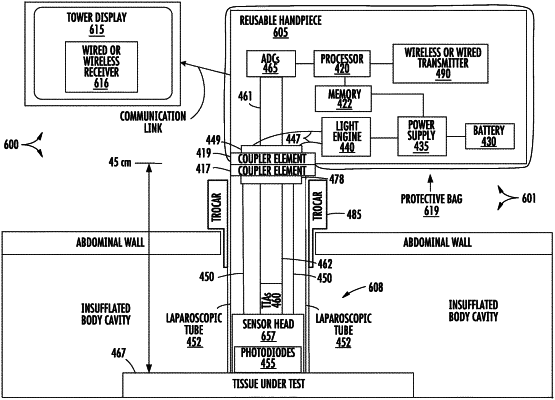
an elongated tube, comprising a proximal end and a distal end, wherein the elongated tube comprises a uniform diameter along a longitudinal direction between the proximal and distal ends, and an opening is at the distal end;
a sensor head, coupled to the opening at the distal end of the elongated tube, wherein the sensor head comprises a surface that is transverse to the longitudinal direction;
an emitter, positioned on the sensor head, wherein the emitter emits light in the longitudinal direction and in a direction away from the surface of the sensor head and away from the proximal end;
a detector, positioned on the sensor head, wherein the detector comprises a light-to-electrical-current converter and faces the opening at the distal end of the elongated tube;
an amplifier circuit, positioned within an interior tubular space of the elongated tube, wherein the amplifier circuit is coupled to the detector closer to the distal end than the proximal end of the elongated tube; and
a first wireless transceiver, coupled to the proximal end of the elongated tube, wherein the first wireless transceiver is outside of the elongated tube.
|