| CPC A61B 17/068 (2013.01) [A61B 17/072 (2013.01); A61B 17/07207 (2013.01); A61B 17/105 (2013.01); A61B 34/71 (2016.02); A61B 2017/0046 (2013.01); A61B 2017/00323 (2013.01); A61B 2017/00327 (2013.01); A61B 2017/00398 (2013.01); A61B 2017/00734 (2013.01); A61B 2017/07214 (2013.01); A61B 2017/07271 (2013.01); A61B 2017/07278 (2013.01); A61B 2017/07285 (2013.01); A61B 2017/2902 (2013.01); A61B 2017/2927 (2013.01); A61B 2017/2933 (2013.01); A61B 2017/2939 (2013.01); A61B 2017/2943 (2013.01); A61B 2017/2946 (2013.01); A61B 2090/0818 (2016.02)] | 20 Claims |

|
1. A surgical instrument, comprising:
an elongate shaft defining a longitudinal axis, wherein said elongate shaft comprises a shaft frame;
an end effector extending from said elongate shaft, wherein said end effector comprises an elongate channel pivotally coupled to said shaft frame of said elongate shaft, wherein said elongate channel is configured for pivotal travel relative to said elongate shaft about an articulation axis that is transverse to said longitudinal axis;
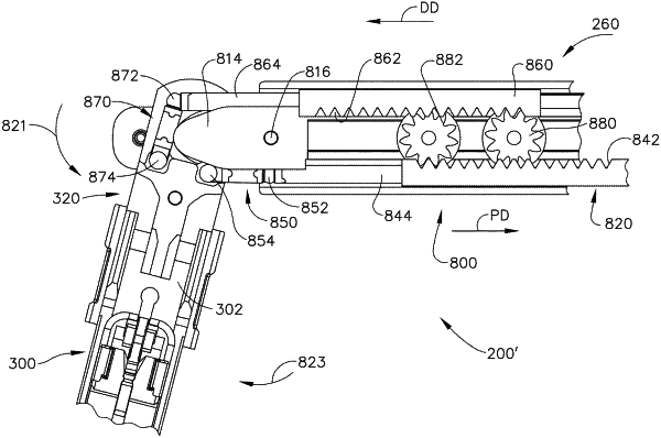
a first articulation driver positioned on a first side of said longitudinal axis, wherein said first articulation driver comprises a first drive rack and a first articulation rod extending from said first drive rack, wherein said first drive rack comprises a plurality of first teeth, and wherein said first articulation rod is pivotally coupled directly to a proximal end of said elongate channel;
a second articulation driver positioned on a second side of said longitudinal axis opposite said first side, wherein said second articulation driver comprises a second drive rack and a second articulation rod extending from said second drive rack, wherein said second drive rack comprises a plurality of second teeth, and wherein said second articulation rod is pivotally coupled directly to said proximal end of said elongate channel;
a pinion gear rotatably supported by said shaft frame and positioned intermediate said first drive rack and said second drive rack, wherein said pinion gear is in meshing engagement with said plurality of first teeth and said plurality of second teeth; and
a proximal articulation driver translatable longitudinally to apply a linear articulation motion to said first articulation driver to translate said first articulation driver, wherein said proximal articulation driver is translatable relative to said first articulation driver, wherein said pinion gear operably couples said first articulation driver and said second articulation driver such that said first articulation driver and said second articulation driver move in opposite directions when said first articulation driver is translated by said proximal articulation driver, and wherein said elongate channel is articulated about said articulation axis when said first articulation driver and said second articulation driver move in opposite directions.
|