| CPC H02K 1/20 (2013.01) [H02K 5/203 (2021.01)] | 17 Claims |

|
1. A motor cooling structure, comprising:
a plurality of branch flow-channels circumferentially arranged on a stator of a motor around an axis of the motor and running through the stator of the motor;
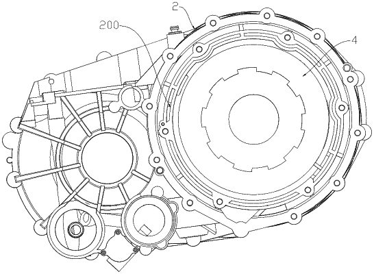
a plurality of shell flow-channels arranged on a side wall of a reducer shell and comprising: a liquid inlet flow-channel, shell long flow-channels, and a liquid outlet flow-channel, wherein the liquid inlet flow-channel, the shell long flow-channels, and the liquid outlet flow-channel are circumferentially arranged on the reducer shell around the axis of the motor;
end cover flow-channels, comprising a plurality of end-cover long flow-channels, and the plurality of end-cover long flow-channels being circumferentially arranged on a motor end cover around the axis of the motor;
wherein the plurality of shell flow-channels, the plurality of branch flow-channels and the end cover flow-channels form a continuous total flow-channel;
a liquid inlet disposed on the reducer shell and in communication with the liquid inlet flow-channel; and
a liquid outlet disposed on the reducer shell and in communication with the liquid outlet flow-channel,
wherein a first resin glue is disposed outside one end of coils of the motor close to the reducer shell, and wherein the first resin glue is located inside a circumference formed by the plurality of shell flow-channels and configured to form a closed space with the reducer shell as a cooling flow-channel for the first resin glue, wherein an inner wall of the liquid outlet flow-channel is defined with an opening, and the opening of the liquid outlet flow-channel and the liquid outlet are respectively arranged on both sides of the first resin glue.
|