| CPC H01J 37/32642 (2013.01) [H01J 37/32807 (2013.01); H01L 21/6835 (2013.01); H01L 21/68721 (2013.01); H01L 21/68735 (2013.01); H01L 21/68742 (2013.01); H01L 2221/68304 (2013.01)] | 26 Claims |
|
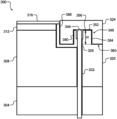
1. An edge ring configured to be raised and lowered relative to a substrate support, via one or more lift pins, in a substrate processing system, wherein the edge ring is further configured to interface with a guide feature extending upward from a bottom ring and/or a middle ring of the substrate support during tuning of the edge ring, the edge ring comprising:
an upper surface;
an annular inner diameter;
an annular outer diameter;
a lower surface; and
an annular groove arranged in the lower surface of the edge ring to interface with the guide feature, wherein walls of the annular groove are substantially vertical,
wherein a depth of the annular groove is at least 50% of a thickness of the edge ring,
wherein the depth of the annular groove is selected according to a tunable range of the edge ring, and
wherein the annular inner diameter of the edge ring defines a substantially vertical inner wall having a height that is substantially the same as a maximum height of the edge ring.
|