| CPC G11C 7/1066 (2013.01) [G11C 7/222 (2013.01); H03K 5/135 (2013.01); H03K 5/1534 (2013.01)] | 20 Claims |

|
1. An electronic device, comprising:
a first input configured to receive a clock signal;
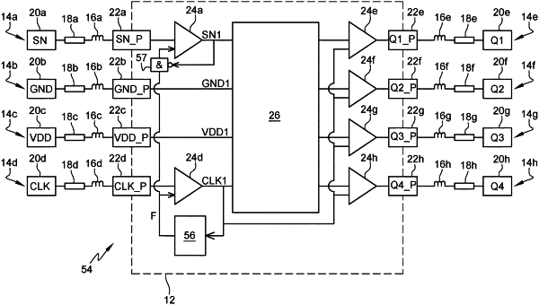
a first input buffer having a data input, a control input, and an output buffer, the data input coupled to the first input, the control input configured to receive a first control signal indicating to the first input buffer to maintain a constant value for a first output voltage at the output buffer of the first input buffer for a first duration after each edge of the clock signal, the first duration being a subset of a period of the clock signal;
a first circuit having a clock input coupled to the output buffer and configured to receive the first output voltage; and
a first output buffer having a first input coupled to an output of the first circuit and a second input coupled to the output buffer, a second output voltage at the first output buffer changing value based on the first output voltage and synchronized on a first edge of the clock signal.
|