| CPC G01R 31/2874 (2013.01) [G01R 31/3025 (2013.01)] | 20 Claims |

|
1. A receiver comprising:
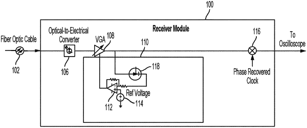
a magnitude correction circuit to receive an electrical signal defined by a phase, wherein the electrical signal is a combined electrical signal comprising a first signal and a second signal, the magnitude correction circuit comprising:
a detector to generate a control signal proportional to received power of the second signal; and
an error amplifier coupled to the detector to compare a reference voltage against an output of the detector to generate a signal proportional to the difference between the reference voltage and the output of the detector to determine an amplification or attenuation of the second signal based on a drift of the electrical signal;
a variable gain amplifier coupled to the magnitude correction circuit, the variable gain amplifier to generate a compensated electrical signal based on the amplification or attenuation of the second signal determined by the magnitude correction circuit; and
a de-modulating mixer coupled to the magnitude correction circuit, the de-modulating mixer to mix a phase compensated signal and the compensated electrical signal.
|