| CPC G01D 5/34 (2013.01) [G06F 3/0362 (2013.01)] | 19 Claims |

|
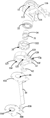
1. A mouse encoder, comprising:
a housing provided with a mounting cavity, wherein an end surface of the housing defines a connection hole connected with a rotation shaft of a scroll wheel, and the connection hole communicates with the mounting cavity;
a rolling bearing member arranged in the mounting cavity and an outer ring of the rolling bearing member fixed to an inner wall surface of the mounting cavity;
a grating member, comprising a rotating cylinder and a grating disk sleeved on the rotating cylinder, wherein the grating disk has a plurality of light transmitting slots arranged along a circumference thereof at intervals, the rolling bearing member is sleeved on the rotating cylinder, and an axis of the connection hole, an axis of the rotating cylinder and an axis of the rolling bearing member all lie in a same straight line; and
a circuit board arranged in the housing, wherein the circuit board is electrically connected with a light emitter and a light receiver, the circuit board is configured to electrically connect with a main board of the mouse, the light emitter is conductive with the light receiver to form an optical path, when the rotating cylinder rotates, the grating disk is driven by the rotating cylinder to block or expose the optical path;
wherein the housing comprises a mounting housing and a fixing housing spaced from the mounting housing, the mounting housing comprises a mounting plate; a mounting portion is arranged on the mounting plate and protrudes in a direction away from the fixing housing, the mounting cavity is formed in the mounting portion, and the connection hole is defined in an end surface of the mounting portion away from the fixing housing.
|