| CPC H04N 25/75 (2023.01) [H01L 27/14612 (2013.01); H04N 5/144 (2013.01); H04N 23/65 (2023.01); H04N 25/633 (2023.01); H04N 25/772 (2023.01); H10K 39/32 (2023.02); B60R 2300/30 (2013.01); B60R 2300/80 (2013.01)] | 17 Claims |

|
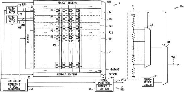
1. A light detecting device comprising:
a first pixel including a first photodiode;
a first signal line coupled to the first pixel, the first signal line extending along a first direction;
a first analog-to-digital converter coupled to the first signal line;
a first control line extending along a second direction;
a signal generator coupled to the first control line;
a first transistor having a source or a drain coupled to the first signal line and a gate coupled to the first control line; and
diagnosis circuitry configured to detect an error based on output generated by the first analog-to-digital converter,
wherein the first analog-to-digital converter is configured to generate a first digital code based on a first signal output from the first pixel in a first period,
wherein the signal generator is configured to output a first control signal to the first control line in a second period,
wherein the first analog-to-digital converter is configured to generate a second digital code based on a second signal output from the first transistor corresponding the first control signal in the second period, and
wherein the diagnosis circuitry is configured to diagnose a first signal path including the first signal line based on the second digital code.
|