| CPC H02P 3/12 (2013.01) [B27B 5/38 (2013.01); H02P 3/22 (2013.01)] | 18 Claims |

|
1. A power tool comprising:
a motor;
a trigger configured to be actuated;
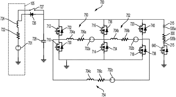
a brake switch connected to the motor;
a brake resistor assembly selectively connected to the motor via the brake switch, the brake resistor assembly including a stamped brake resistor, the stamped brake resistor including a terminal portion and a resistive portion, wherein the resistive portion includes a planar serpentine path forming a plurality of leaves and a gap between each leaf, the resistive portion further including a first leg, a second leg perpendicular to the first leg, a third leg, and a fourth leg perpendicular to the third leg, and wherein the planar serpentine path includes a filling substance located within each gap formed between adjacent leaves, the filling substance configured to maintain a shape of the stamped brake resistor; and
a controller including an electronic processor and a memory, the controller connected to the trigger, the motor, and the brake switch, the controller configured to:
control power delivered to the motor based on a position of the trigger,
determine to brake the motor during operation of the motor, and
activate, in response to determining to brake the motor, the brake switch to connect the stamped brake resistor to the motor.
|