| CPC H02M 3/1586 (2021.05) [H02M 1/0003 (2021.05); H02M 1/0009 (2021.05); H02M 3/157 (2013.01); H02M 3/1584 (2013.01); H02M 1/08 (2013.01)] | 18 Claims |

|
1. An apparatus comprising:
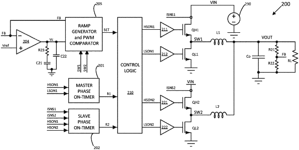
a ramp generator configured to produce a set signal for determining a phase shift between a first phase and a second phase of a power converter;
a first phase on-timer configured to produce a first reset signal for determining a turn-on time of a high-side switch of the first phase of the power converter, wherein the first phase on-timer comprises a first current source and a first capacitor connected in series between an input of the power converter and ground, and wherein a current flowing through the first current source is proportional to an input voltage of the power converter, and wherein the input of the power converter is directly connected to the high-side switch of the first phase of the power converter, and wherein the first phase on-timer further comprises a switch connected in parallel with the first capacitor, and wherein a gate of the switch is controlled by a gate drive signal of a low-side switch of the first phase of the power converter, and a comparator having a non-inverting input connected to a common node of the first current source and the first capacitor, an inverting input configured to receive a reference voltage equal to a product of the input voltage of the power converter and a duty cycle of the power converter, and an output configured to generate the first reset signal;
a second phase on-timer configured to produce a second reset signal for determining a turn-on time of a high-side switch of the second phase of the power converter; and
a control logic block configured to generate gate drive signals for the first phase and the second phase of the power converter based on the set signal, the first reset signal and the second reset signal.
|