| CPC H02M 3/06 (2013.01) [G05D 23/24 (2013.01); H02M 1/0019 (2021.05); H02M 3/158 (2013.01)] | 8 Claims |

|
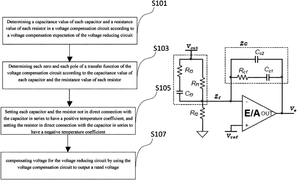
1. A voltage compensation method of a voltage reducing circuit, comprising the following steps:
determining a capacitance value of each capacitor and a resistance value of each resistor in a voltage compensation circuit according to a voltage compensation expectation of the voltage reducing circuit;
determining each zero and each pole of a transfer function of the voltage compensation circuit according to the capacitance value of each capacitor and the resistance value of each resistor;
setting each capacitor and the resistor not in direct connection with the capacitor in series to have a positive temperature coefficient, and setting the resistor in direct connection with the capacitor in series to have a negative temperature coefficient, wherein the positive and negative temperature coefficients are set to enable a variable quantity, generated when a temperature change occurs, of each zero and each pole of the transfer function of the voltage compensation circuit to not exceed a predetermined fluctuation range; and
compensating voltage for the voltage reducing circuit by using the voltage compensation circuit to output a rated voltage;
wherein the voltage compensation circuit comprises resistors (Rc1), (Rf1), (Rf2), (Rf3) and capacitors (Cc1), (Cc2), (Cf3), wherein the resistor Rf3 and the capacitor Cf3 are connected in series and then are connected in parallel with the resistor Rf1 between an output voltage and an inverting input terminal of a comparator; the resistor Rc1 and the capacitor Cc1 are connected in series and then are connected in parallel with the capacitor Cc2 between the inverting input terminal and an inverting output terminal of the comparator; and the inverting input terminal of the comparator is grounded through the resistor Rf2;
wherein the capacitors Cc1, Cc2, Cf3 are capacitors having a positive temperature coefficient; the resistors Rf1, Rf2 are resistors having a positive temperature coefficient; and the resistors Rc1, Rf3 are resistors having a negative temperature coefficient;
according to a zero-pole calculation formula of the transfer function of the compensation circuit, resistance values of themistors having a negative temperature coefficient increase when the capacitance values of the capacitors having a positive temperature coefficient decrease with temperature, so that each zero and pole of the transfer function of the compensation circuit are stabilized within a certain range.
|