| CPC H02K 1/2766 (2013.01) [H02K 29/03 (2013.01); H02K 2213/03 (2013.01)] | 14 Claims |

|
1. A rotating electrical machine comprising:
a rotor having a rotor core provided with a plurality of magnet holes in a circumferential direction, and permanent magnets embedded in the magnet holes and forming magnetic poles; and
a stator having a plurality of tooth portions which are disposed in the circumferential direction and on which coils are wound, wherein
the rotor is disposed on an inner circumferential side of the stator with a magnetic gap therebetween,
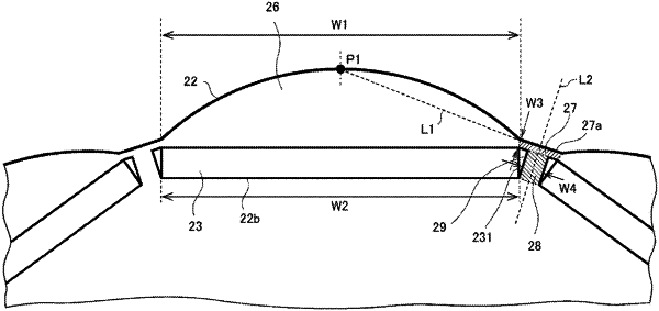
an outer circumferential portion of the rotor core has petal portions disposed so as to correspond to the respective magnetic poles and each having an arc shape with a diameter smaller than a rotor diameter, and interpole bridges each located at a non-magnetic portion between the adjacent magnetic poles and disposed on an outer circumferential side with respect to the permanent magnets,
the interpole bridges each have an outer circumferential surface facing the magnetic gap and formed by two flat surfaces, and
the two flat surfaces are arranged at an angle to each other such that a connection portion between the two flat surfaces is recessed with respect to the magnetic gap.
|