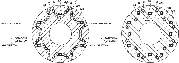
| CPC H02K 1/276 (2013.01) [H02K 1/223 (2013.01); H02K 1/27 (2013.01); H02K 1/2766 (2013.01); H02K 13/02 (2013.01)] | 11 Claims |

|
1. A rotating electric machine, comprising:
a stator; and
a rotor provided so as to be rotatable relative to the stator,
wherein the rotor includes:
a rotor core;
an axial end part provided at an end portion of the rotor core in an axial direction of the rotor; and
a rotor magnet that is inserted into an insertion hole formed so as to pass through the rotor core in the axial direction, and is fixed to both of the rotor core and the axial end part,
wherein the axial end part has a recessed portion in which an end portion of the rotor magnet in the axial direction is to be inserted,
wherein the rotor magnet includes, as side surfaces along the axial direction, a first side surface and a second side surface different from the first side surface,
wherein the first side surface is, of the two side surfaces perpendicular to a magnetization direction of the rotor magnet, the side surface located on an outer side in a radial direction of the rotor,
wherein the second side surface is the side surface parallel to the magnetization direction of the rotor magnet,
wherein the first side surface is fixed to a first inner wall surface of the insertion hole opposed to the first side surface,
wherein in a cross section perpendicular to the axial direction, a width of the first inner wall surface along the first side surface is larger than a width of the first side surface,
wherein the second side surface is fixed to a second inner wall surface of the recessed portion opposed to the second side surface,
wherein in the cross section perpendicular to the axial direction, a width of the second inner wall surface along the second side surface is larger than a width of the second side surface,
wherein the rotor magnet is fixed to the rotor core through surface joining between the first side surface and the first inner wall surface,
wherein the rotor magnet is fixed to the axial end part through surface joining between the second side surface and the second inner wall surface, and
wherein the first side surface is arranged so as to be opposed to an inner wall surface of the recessed portion with an interspace between the first side surface and the inner wall surface.
|