| CPC H02J 7/02 (2013.01) [H02J 50/12 (2016.02); H02M 1/0058 (2021.05); H02M 7/219 (2013.01)] | 20 Claims |

|
1. A receive end of a wireless charging system, the receive end comprising a receive coil, a receive end compensation circuit, a rectifier, and a controller, wherein:
the receive coil is configured to receive an alternating magnetic field and output an alternating current;
the receive end compensation circuit is connected between the receive coil and the rectifier, wherein the receive end compensation circuit is configured to:
compensate the alternating current that is output by the receive coil; and
output a compensated alternating current to the rectifier;
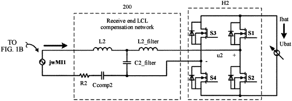
the receive end compensation circuit and the receive coil form a receive end compensation network, wherein the receive end compensation network comprises a first branch, a second branch, and a third branch, wherein the first branch comprises the receive coil, wherein both the first branch and the second branch are inductive branches, wherein a reactance of the second branch is greater than that of the first branch, wherein the first branch is connected to a first input end of the rectifier through the second branch, wherein the third branch is a capacitive branch, wherein a first end of the third branch is connected to a common end of the first branch and the second branch, and wherein a second end of the third branch is connected to a second input end of the rectifier;
the rectifier comprises controllable switching transistors, wherein the rectifier is configured to rectify the alternating current to a direct current; and
the controller is configured to:
adjust a phase difference between a first bridge arm and a second bridge arm of the rectifier; and
adjust a phase-shift angle between a bridge arm voltage of the rectifier and a fundamental component of an input current of the rectifier, wherein zero-voltage switching is implemented for the controllable switching transistors of the rectifier.
|