| CPC H02J 7/007 (2013.01) [B60L 50/60 (2019.02); B60L 50/51 (2019.02); B60L 2220/40 (2013.01); H02J 7/0024 (2013.01)] | 18 Claims |

|
1. A control method for an electric vehicle battery voltage regulation system, characterized in that
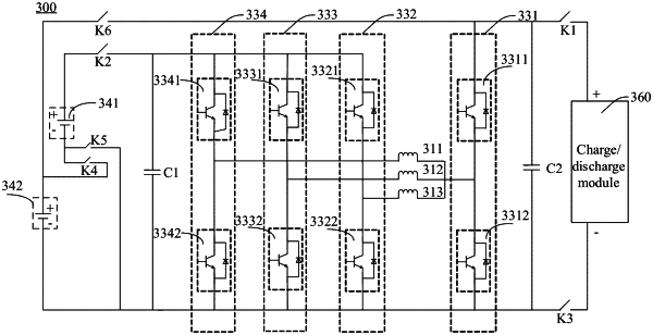
the electric vehicle battery voltage regulation system comprises an electric vehicle battery, a motor, a bridge module, and a switch assembly; wherein
the electric vehicle battery comprises a first electric vehicle battery group and a second electric vehicle battery group;
the bridge module comprises a first leg and a second leg set, the first leg and all legs in the second leg set each comprise an upper leg and a lower leg, a joint between the upper leg and the lower leg of the first leg is connected to a joint of all windings of the motor, and joints between upper legs and lower legs of all the legs in the second leg set are connected to all the windings of the motor, respectively; and
the switch assembly comprises a first switch, a second switch, a third switch, a fourth switch, and a fifth switch, wherein one end of the first switch is connected to a positive terminal of a charge/discharge module, the other end of the first switch is connected to the upper leg of the first leg, one end of the second switch is connected to a joint of the upper legs of all the legs in the second leg set, the other end of the second switch is connected to a positive terminal of the first electric vehicle battery group, one end of the third switch is connected to the lower leg of the first leg, the other end of the third switch is connected to a negative terminal of the charge/discharge module, one end of the fourth switch is connected to a negative terminal of the first electric vehicle battery group, the other end of the fourth switch is connected to a positive terminal of the second electric vehicle battery group, one end of the fifth switch is connected to the negative terminal of the first electric vehicle battery group, and the other end of the fifth switch is connected to a joint of the lower legs of all the legs in the second leg set; and
the control method comprises:
controlling the first switch, the second switch, the third switch, the fourth switch, the fifth switch, the first leg, and the second leg set to turn on or off, to form in a first period a circuit loop for the charge/discharge module to discharge to the motor and to form in a second period a circuit loop for the charge/discharge module and the motor to charge the first electric vehicle battery group and the second electric vehicle battery group or form in the second period a circuit loop for the motor to charge the first electric vehicle battery group and the second electric vehicle battery group; or
controlling the first switch, the second switch, the third switch, the fourth switch, the fifth switch, the first leg, and the second leg set to turn on or off, to form in a third period a circuit loop for the first electric vehicle battery group and the second electric vehicle battery group to discharge to the motor and to form in a fourth period a circuit loop for the first electric vehicle battery group, the second electric vehicle battery group, and the motor to discharge to the charge/discharge module or form in the fourth period a circuit loop for the motor to discharge to the charge/discharge module.
|