| CPC H01R 13/639 (2013.01) [H01R 2105/00 (2013.01)] | 19 Claims |

|
1. An air hose coupling securing apparatus for securing an air hose coupling to another air hose coupling, the apparatus comprising:
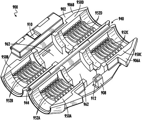
a. a shell defining a primary cavity therein, the shell further comprising a first shell member and a second shell member wherein the first shell member is hingedly attached to the second shell member and wherein the shell can be situated in an open configuration or a closed configuration; and
b. a plurality of flexible inserts including a first flexible insert located in the first shell member and configured to fit tightly within the first shell member, the first flexible insert further comprising at least one first flexible insert flexible rib and a first flexible insert base, wherein the first flexible insert flexible rib is biased away from the first flexible insert base; a second flexible insert located in the second shell member and configured to fit tightly within the second shell member, the second flexible insert further comprising at least one second flexible insert flexible rib and a second flexible insert base, wherein the second flexible insert flexible rib is biased away from the second flexible insert base; a third flexible insert located in the first shell member and configured to fit tightly within the first shell member, the third flexible insert further comprising at least one third flexible insert flexible rib; and a fourth flexible insert located in the second shell member and configured to fit tightly within the second shell member, the fourth flexible insert further comprising at least one fourth flexible insert flexible rib.
|