| CPC H01H 13/14 (2013.01) [G08C 17/02 (2013.01); H01H 9/0271 (2013.01); H01H 13/04 (2013.01); H01H 13/20 (2013.01)] | 2 Claims |

|
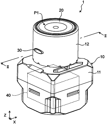
1. A wireless switch, comprising:
a switch body;
a push button connected to the switch body in a state of being movable along an approaching/separating direction that the push button is closer to and away from the switch body, between a non-operating position away from the switch body and an operating position closer to the switch body than the non-operating position;
a signal output device accommodated in the switch body and configured to output a switch signal in response to a movement of the push button from the non-operating position to the operating position; and
a restriction member that restricts the movement of the push button from the non-operating position to the operating position when the push button is located at the non-operating position, wherein
the restriction member is configured to be movable between a restriction position and a release position along an operating direction intersecting the approaching/separating direction when the push button is located at the non-operating position, the restriction position being a position that the restriction member is disposed between the switch body and the push button in the approaching/separating direction and a restriction on the movement of the push button from the non-operating position to the operating position is imposed, and the release position being a position that the restriction is released,
the restriction member includes:
a main body unit disposed to be movable along the operating direction between the restriction position and the release position; and
an operation unit connected to the main body unit, the operation unit being capable of moving the main body unit from the restriction position to the release position by a movement of the operation unit in the operating direction,
the wireless switch comprises a cover member surrounding the push button in the approaching/separating direction,
the main body unit extends in the operating direction along an inner surface of the cover member, the inner surface opposing the push button,
the cover member includes a guide unit on the inner surface opposing the push button, the guide unit being configured as a groove to accommodate the main body unit and guide the movement of the main body unit in the operating direction,
the release position is arranged farther from the push button than the restriction position in the operating direction, and
the guide unit is configured as a bottomed groove to accommodate the main body unit.
|