| CPC G09G 3/2092 (2013.01) [G09G 2310/0267 (2013.01); G09G 2310/0289 (2013.01); G09G 2330/021 (2013.01); G09G 2330/04 (2013.01)] | 11 Claims |

|
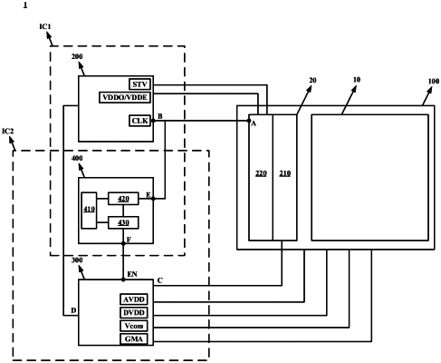
1. A protection circuit for a display device, the display device comprising a gate driving circuit, a level shift circuit, and a power management circuit, the level shift circuit being configured to provide an input signal to a signal input terminal of the gate driving circuit, the power management circuit being configured to provide power to the gate driving circuit,
wherein the protection circuit is configured to provide a power control signal to the power management circuit based on a current at the signal input terminal of the gate driving circuit, so that the power management circuit stops providing the power to the gate driving circuit;
wherein the protection circuit comprises a control circuit, a current detection circuit, a comparison circuit, a current detection terminal and a control signal output terminal,
the current detection terminal is configured to receive the current at the signal input terminal of the gate driving circuit,
the control signal output terminal is configured to provide the power control signal to the power management circuit,
the control circuit is coupled to the current detection circuit and the comparison circuit, and configured to send a first control signal to the current detection circuit to control an operation of the current detection circuit and send a second control signal to the comparison circuit to control an operation of the comparison circuit,
the current detection circuit is coupled to the current detection terminal and the comparison circuit, and configured to detect the current at the signal input terminal of the gate driving circuit under a control of the control circuit, and send the detected current to the comparison circuit, and
the comparison circuit is coupled to the control signal output terminal, and configured to compare the current to a first threshold under a control of the control circuit, and to generate the power control signal at the control signal output terminal based on a comparison result;
wherein generating the power control signal based on the comparison result comprises: generating the power control signal at the control signal output terminal when the current is greater than the first threshold;
wherein the control circuit is further configured to receive and store control parameters; and
wherein the control parameters comprise the first threshold and a detection time, and wherein the detection time is a time interval between a transition edge of a voltage signal at the signal input terminal to be detected from the gate driving circuit and a timing when the current is detected.
|