| CPC G06T 7/285 (2017.01) [G06F 18/213 (2023.01); G06N 3/04 (2013.01); G06N 3/08 (2013.01); G06T 7/593 (2017.01); G06T 7/62 (2017.01); G06T 7/75 (2017.01); G06T 7/85 (2017.01); G06V 10/449 (2022.01); G06V 10/757 (2022.01); G06V 10/82 (2022.01); G06V 20/41 (2022.01); G06V 20/54 (2022.01); G08G 1/0175 (2013.01); G08G 1/056 (2013.01); H04N 13/239 (2018.05); H04N 13/246 (2018.05); H04N 23/64 (2023.01); G06T 2207/10021 (2013.01); G06T 2207/20081 (2013.01); G06T 2207/20084 (2013.01); G06T 2207/30241 (2013.01); G06T 2207/30244 (2013.01)] | 12 Claims |

|
1. A method for intelligently measuring vehicle trajectory based on a binocular stereo vision system, comprising:
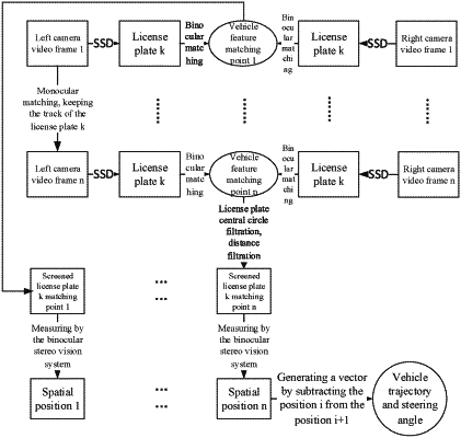
step 1, inputting a dataset of images containing license plates into a SSD neural network, and training the SSD neural network with license plate as a detection feature to obtain a license plate recognition model;
step 2, installing the binocular stereo vision system on the right side, middle or above a lane, calibrating the binocular stereo vision system to acquire internal and external parameters of two cameras; and recording videos of moving target vehicles by the calibrated binocular stereo vision system;
step 3, detecting license plates in video frames recorded in step 2 with the license plate recognition model trained in step 1, and locating license plate positions of target vehicles;
step 4, performing feature point extraction and stereo matching on license plates in subsequent frames of a same camera by a feature-based matching algorithm, and reserving correct matching points after filtering with a homography matrix; performing feature point extraction and stereo matching on license plates in corresponding left-view and right-view video frames of the binocular stereo vision system by a feature-based matching algorithm, and reserving correct matching points after filtering with a homography matrix;
step 5, screening the reserved matching points in step 4 by a distance measurement method of the binocular stereo vision system, and reserving one closest to a license plate center as the position of a target vehicle in a current frame;
step 6, performing stereo measurement on the screened matching points by the binocular stereo vision system to get spatial position coordinates of vehicle in the video frames; and generating a moving trajectory of the vehicle in time sequence, wherein a calibration method for the binocular stereo vision system in the step 2 comprises: calibrating the two cameras with Zhengyou Zhang's calibration method to acquire their respective parameters such as coordinates of optical center, focal length, scale factor and/or lens distortion; after acquiring the parameters of the two cameras, calibrating the binocular stereo vision system with Zhengyou Zhang's calibration method again to acquire a displacement and rotation angle of a right-view camera relative to a left-view camera, wherein the calibration method for the binocular stereo vision system with Zhengyou Zhang's calibration method comprises: taking the left-view camera as the reference, calibrating with Zhengyou Zhang's calibration method to acquire the external parameters (relative translation vector T1=(l,m,n)T and relative rotation vector V=(α,β,γ)T)) of the right-view camera and the internal parameters (focal length, optical-axis angle, and distortion) of the two cameras themselves, wherein, l,m,n refer to displacements of the right-view camera relative to the left-view camera in three directions of x, y and z respectively, α,β,γ refer to the rotation angles of the right-view camera relative to the left-view camera around three axes of x, y and z respectively, wherein a convergence point of the binocular stereo vision system is determined according to the external parameters:
 wherein, B is a baseline length between the two cameras, and ε indicates the angle between the optical axes of the two cameras, wherein a transformation model is established for a target angle, and imaging points of the same space point in the two cameras are respectively called a left corresponding point and a right corresponding point, which are intersections of the left-view camera and the right-view camera's optical axes and their respective imaging planes, α′ represents a difference between the left corresponding point and the convergence point in the u direction of the image coordinate system, and b′ represents a difference between the right corresponding point and the convergence point in the u direction of the image coordinate system when the left corresponding point or the right corresponding point is on the left side of the convergence point, a difference value is less than 0, otherwise a difference is greater than 0, wherein the optical axes are perpendicular to their respective imaging planes, a line connecting the optical center to the target point is called corresponding axis, and angles α and b between the corresponding axes and the optical axes is calculated as:
 wherein, fl and fr indicate a focal length of the left-view camera and the right-view camera respectively, wherein when the target point is in region I, a target angle c can be calculated as
 the world coordinates of a target point P in region I are (x, y, z), and a depth calculation model for the target point P are being established as:
 wherein a world coordinate x can be calculated with the depth calculation model for the target point P as:
 wherein a world coordinate y can be calculated according to a relation between the left corresponding point and the right corresponding point in the image coordinate system and a relation between the image coordinate system and a world coordinate system, wherein the world coordinates of the target point P are:
 wherein, v′ indicates the pixel difference between the target point and the image center in a longitudinal direction of the image coordinate system, and fl is the focal length of the left-view camera, similarly, world coordinates of the target point in region II, region III and region IV are calculated.
|