| CPC G01S 17/58 (2013.01) [G01S 7/487 (2013.01); G01S 7/4812 (2013.01); G01S 7/4815 (2013.01); G01S 7/4817 (2013.01); G01S 7/4863 (2013.01); G01S 17/95 (2013.01)] | 2 Claims |

|
1. A laser radar device comprising:
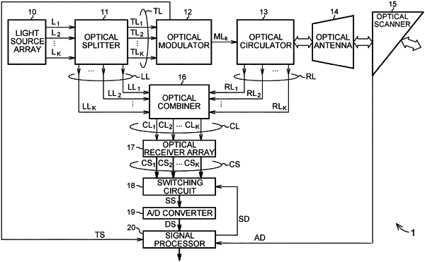
a light source array having a single reference light source configured to emit a reference laser beam, an optical splitting element configured to split the reference laser beam into a plurality of laser light beams, and a plurality of light emitting ends, the light source array being configured to simultaneously emit the plurality of laser light beams from the plurality of light emitting ends, respectively;
an optical splitter configured to separate a plurality of transmission light components from the plurality of laser light beams, respectively, and configured to separate a plurality of local light components from the plurality of laser light beams, respectively;
an optical modulator configured to modulate one of the transmission light components to generate modulated transmission light;
a transmission/reception optical system configured to receive, as received light, the modulated transmission light reflected by a target existing in external space, while scanning the external space with the modulated transmission light;
an optical combiner configured to generate a plurality of interference light components by combining the received light and the plurality of local light components;
an optical receiver array including a plurality of optical receivers arranged at respective positions that optically correspond to different receiving fields of view of the transmission/reception optical system, and configured to generate a plurality of detection signals by detecting the plurality of interference light components;
a switching circuit configured to select a detection signal from among the plurality of detection signals corresponding to the different receiving fields of view, in accordance with a scanning speed of the transmission/reception optical system with respect to the external space; and
a signal processor configured to calculate a signal spectrum of the selected detection signal, and calculate an observation quantity including a velocity vector of the target on a basis of the signal spectrum,
wherein the signal processor includes:
a signal divider configured to divide the detection signal selected by the switching circuit into a plurality of time domain signals indicating respective signal waveforms of a plurality of gate time domains;
a domain converter configured to convert the plurality of time domain signals into a plurality of frequency domain signals, respectively;
an integrator configured to calculate a plurality of spectra of the plurality of the time domain signals from the plurality of frequency domain signals, and calculate the signal spectrum by integrating the plurality of spectra; and
an observation quantity calculator configured to calculate the observation quantity on a basis of the signal spectrum.
|