| CPC G01R 31/34 (2013.01) [H02M 1/0009 (2021.05); H02M 3/155 (2013.01)] | 17 Claims |

|
1. A testing circuit for a plurality of SMs of a cascaded converter, comprising:
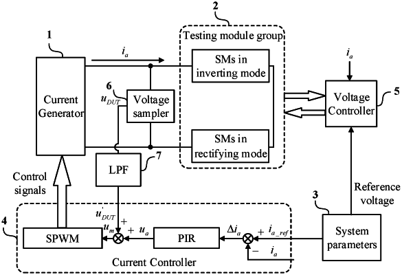
a current generator and a testing module group, wherein the current generator provides a testing current to the testing module group; wherein the testing module group adopts any of the following forms:
the testing module group comprises two testing arms, each of the two testing arms comprises a plurality of tested SMs connected in series, and the two testing arms are in a reverse series connection structure, in which DC voltage components in capacitor voltages of the plurality of tested SMs of said two testing arms are equal in magnitude but opposite in direction; the plurality of tested SMs, in each of the two testing arms, implement both rectifying and inverting operating conditions of the cascaded converter respectively; the two testing arms have identical structures or different structures;
the testing module group comprises one or more testing units, and the one or more testing units are connected in series; each testing unit comprises two tested SMs connected in series reversely, in which DC voltage components in capacitor voltages of the two tested SMs are equal in magnitude but opposite in direction, wherein the two tested SMs implement both the rectifying and inverting operating conditions of the cascaded converter respectively;
the testing module group and internal tested SMs of the testing module group are arranged in any order in the testing circuit, wherein an electrical connection relationship remain unchanged; when the testing module group receives the testing current generated by the current generator, the testing module group emulates a voltage signal of the plurality of SMs in the cascaded converter, or emulates the voltage signal and a current signal of the plurality of SMs in the cascaded converter,
wherein the current generator comprises: a single-phase converter and a filter; wherein:
when the testing module group comprises the two testing arms with the identical structures, a first end of the single-phase converter is connected to an input end of the filter, and an output end of the filter is connected to an input end of a second testing arm of the two testing arms, a second end of the single-phase converter is connected to an input end of a first testing arm of the two testing arms in series, and output ends of the two testing arms are mutually connected; a series sequence of the single-phase converter, the filter, and the two testing arms are changeable into different configurations;
when the testing module group comprises the one or more testing units, the first end of the single-phase converter is connected to the input end of the filter, and the output end of the filter is connected to a first input end of the one or more testing units in series connection the second end of the single-phase converter is connected to a second input end of the one or more testing units in series connection; the series sequence of the single-phase converter, the filter, and the one or more testing units are changeable into the different configurations.
|