| CPC F25B 41/40 (2021.01) [F25B 41/24 (2021.01); F25B 49/02 (2013.01); F25B 2345/002 (2013.01); F25B 2500/222 (2013.01); F25B 2600/2515 (2013.01)] | 14 Claims |

|
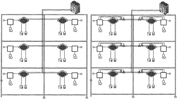
1. A multi-air conditioner for heating/cooling operation, the multi-air conditioner comprising:
at least one indoor unit which is installed in a room, and comprises an indoor heat exchanger;
an outdoor unit which is connected to the indoor unit through a refrigerant pipe, and comprises an outdoor heat exchanger, a compressor, an outdoor expansion valve, and a four-way valve;
at least one leakage blocking valve which is formed on the refrigerant pipe, and blocks a refrigerant flow in the refrigerant pipe when a refrigerant leak occurs from the refrigerant pipe in the room; and
a buffer unit which is installed on the refrigerant pipe between the indoor unit and the outdoor unit, and is configured to collect refrigerant leaking from the refrigerant pipe, wherein the buffer unit comprises:
a buffer tank configured to collect the refrigerant flowing in the refrigerant pipe;
a low-pressure buffer pipe disposed outside of the buffer tank and extends through a top of the buffer tank to a bottom portion of the buffer tank and is configured to set a low pressure in the buffer tank by allowing a flow of the low-pressure buffer pipe; and
a high-pressure buffer pipe disposed outside of the buffer tank and extends through the top of the buffer tank to an upper portion of the buffer tank and is configured to set a high pressure in the buffer tank by allowing a flow of the high-pressure buffer pipe, wherein the refrigerant pipe comprises:
a liquid pipe connection pipe through which a high-pressure liquid refrigerant is to flow;
a gas pipe connection pipe through which a high-pressure gas refrigerant is to flow; and
a common pipe through which a low-pressure gas refrigerant of low pressure is to flow from the outdoor unit,
wherein the common pipe is connected to the low-pressure buffer pipe to set a low pressure in the buffer tank by allowing the flow of the low-pressure buffer pipe,
wherein the buffer unit includes a first buffer valve to open and close the flow of the high-pressure buffer pipe, and a second buffer valve to open and close the flow of the low-pressure buffer pipe, and
the first and second buffer valves are configured to be opened while the at least one leakage blocking valve is in the process of closing such that the low pressure is set in the bottom of the buffer tank by the low-pressure buffer pipe, the high pressure is set in the upper portion of the buffer tank by the high-pressure buffer pipe, and pressure difference between the low pressure and the high pressure is to collect the high-pressure liquid refrigerant in the buffer tank prior to closing of the at least one leakage blocking valve.
|