| CPC F25B 39/04 (2013.01) [F28D 1/053 (2013.01); F28F 1/02 (2013.01); F28F 9/02 (2013.01)] | 12 Claims |

|
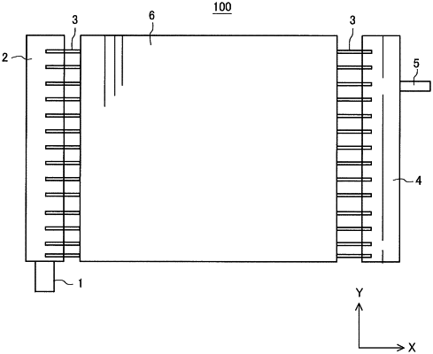
1. A gas header connected to a plurality of flat pipes at one end portion of each of the plurality of flat pipes, the plurality of flat pipes being spaced from each other and arranged in an up-down direction, the gas header being connected to a refrigerant pipe, refrigerant flowing out through the refrigerant pipe when refrigerant flows in through the plurality of flat pipes, refrigerant flowing out through the plurality of flat pipes when refrigerant flows in through the refrigerant pipe, the gas header comprising:
a first tubular portion including a flow passage for refrigerant extending in the up-down direction; and
a second tubular portion including a flow passage having a sectional area smaller than a sectional area of the flow passage of the first tubular portion,
the first tubular portion and the second tubular portion being integrated with each other,
the one end portion of each of the plurality of flat pipes being inserted midway from one direction along a horizontal direction into an inner portion of the first tubular portion,
the second tubular portion being provided across the first tubular portion from the plurality of flat pipes in the horizontal direction,
the second tubular portion being connected at a position midway in the up-down direction and upper than a center of the second tubular portion in the up-down direction to the refrigerant pipe,
a wall between the first tubular portion and the second tubular portion having a first hole opening and extending in the horizontal direction at a portion connected to the refrigerant pipe and a second hole through which the first tubular portion and the second tubular portion communicate with each other at a portion lower than the first hole and having a hole diameter smaller than a hole diameter of the first hole,
an end portion of at least one flat pipe of the plurality of flat pipes inserted into the first tubular portion being positioned at a position lower than the second hole.
|